Microprocessor protected against stack overflow

Inactive Publication Date: 2013-01-10
STMICROELECTRONICS SRL
View PDF21 Cites 45 Cited by
  • Summary
  • Abstract
  • Description
  • Claims
  • Application Information

AI Technical Summary

Benefits of technology

[0010]It may therefore be desired to reinforce the security offered

Problems solved by technology

This technique considerably increases the difficulty of exploiting stack overflow, since it relates to the attacker taking control of the instruction pointer by complex means.
Nevert

Method used


Image

  • Microprocessor protected against stack overflow
  • Microprocessor protected against stack overflow
  • Microprocessor protected against stack overflow

Examples


Embodiment Construction

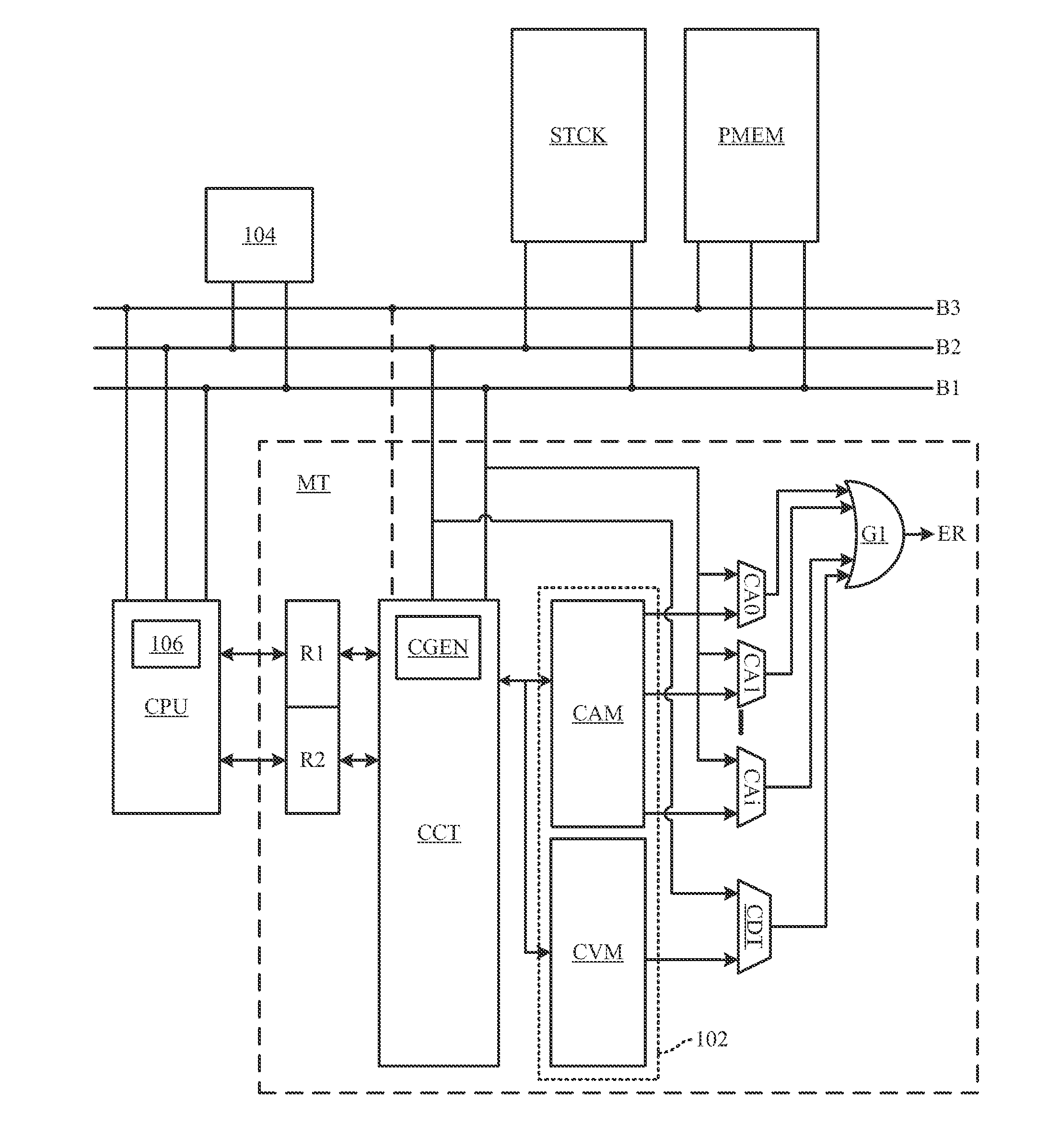
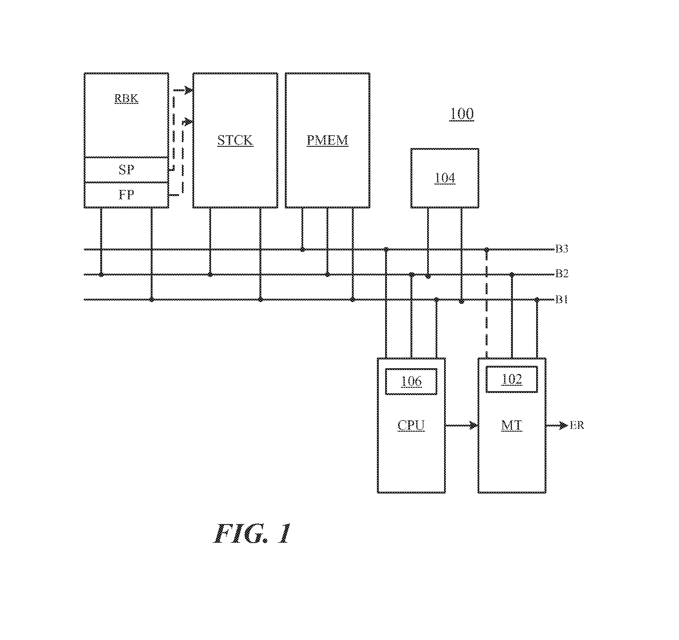
[0026]FIG. 1 shows a microprocessor 100 according to one embodiment. The microprocessor 100 includes a central processing unit CPU, hereinafter “the CPU”, a program memory PMEM, a call stack STCK, and a registry bank RBK. These different elements are linked by an address bus B1, a data bus B2, and an instruction bus B3.

[0027]Registry bank RBK includes a stack pointer register SP and a frame pointer register FP. The stack pointer contains the address of the top of the stack STCK and the frame pointer contains the start address of a frame of a function being executed. Program memory PMEM contains a program executed by the CPU.

[0028]It will be noted that instruction bus B3 is an optional microprocessor element, its provision particular to the architecture used, here the Harvard architecture. A Von Neumann architecture only includes bus B2 to convey both the data and the instructions.

[0029]The microprocessor 100 also includes a stack monitor MT according to one embodiment. Monitor MT is...


PUM


Abstract

A microprocessor includes a central processing unit, at least one call stack, a stack pointer, an address bus, and a data bus. The microprocessor further includes a hardware monitor configured to supply protection codes, insert the protection codes in the stack or let the central processing unit insert them, and then generate an error signal in response to an attempt to modify a protection code present in the stack.

Description

BACKGROUND[0001]1. Technical Field[0002]The present disclosure relates to the protection of a microprocessor against stack overflow. The call stack of a microprocessor is a volatile memory zone directed to the storage of data concerning functions executed by the microprocessor. In particular, the stack allows the storage of an address to which the microprocessor should return after having executed a function.[0003]2. Description of the Related Art[0004]When a first function or “call function” calls a second function or “called function”, the call function places its return address in the stack. When the called function has finished the task for which it was designed, it fetches the return address from the stack. When the functions call each other, return addresses accumulate in the stack and are fetched one after the other after the execution of a function. Besides return addresses, the stack receives data associated with call or called functions, such as local variables of the call...

Claims


Application Information

Patent Timeline
IPC IPC(8): G06F11/07
CPCG06F21/52G06F2221/2153G06F2221/2123G06F9/00
Inventor GUILLEMIN, PIERREORLANDO, WILLIAM
Owner STMICROELECTRONICS SRL
Why Eureka
Try Eureka