Meter puller with safety shield

Inactive Publication Date: 2013-01-17
KILVERT
View PDF6 Cites 5 Cited by
  • Summary
  • Abstract
  • Description
  • Claims
  • Application Information

AI Technical Summary

Benefits of technology

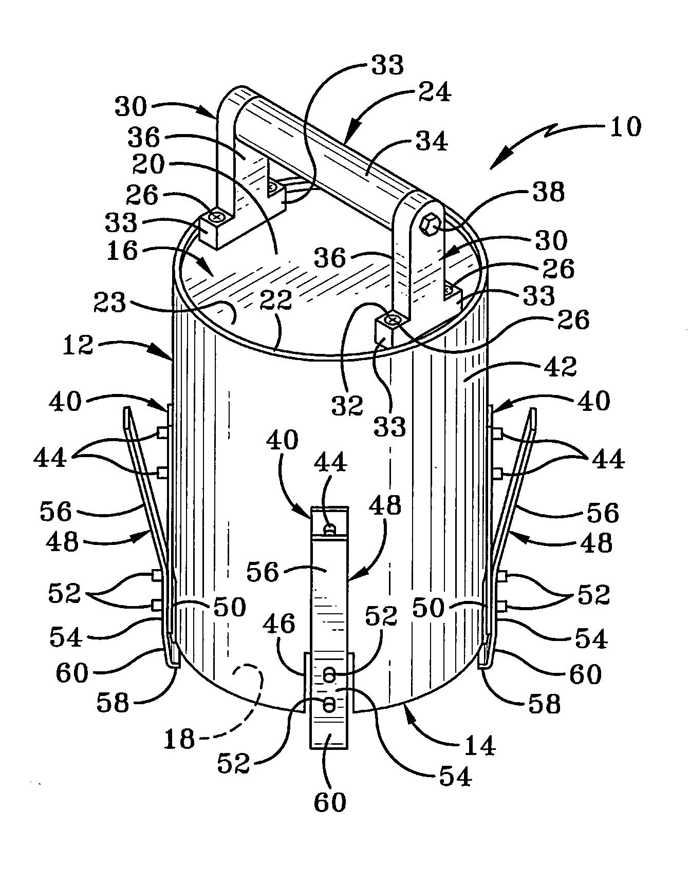
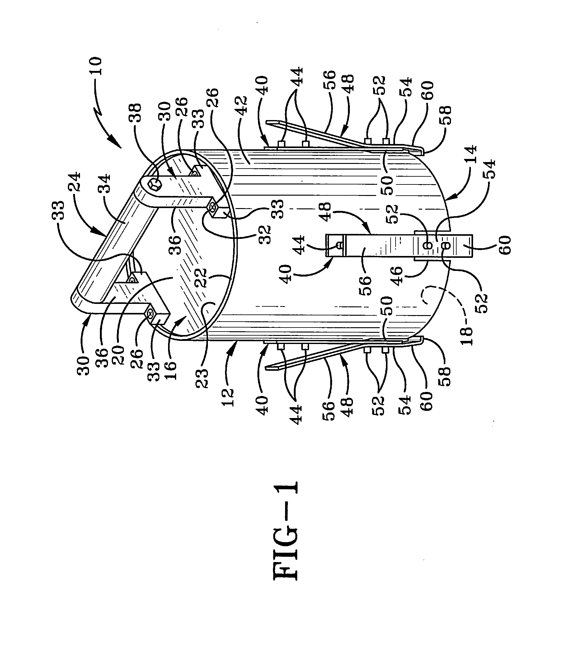
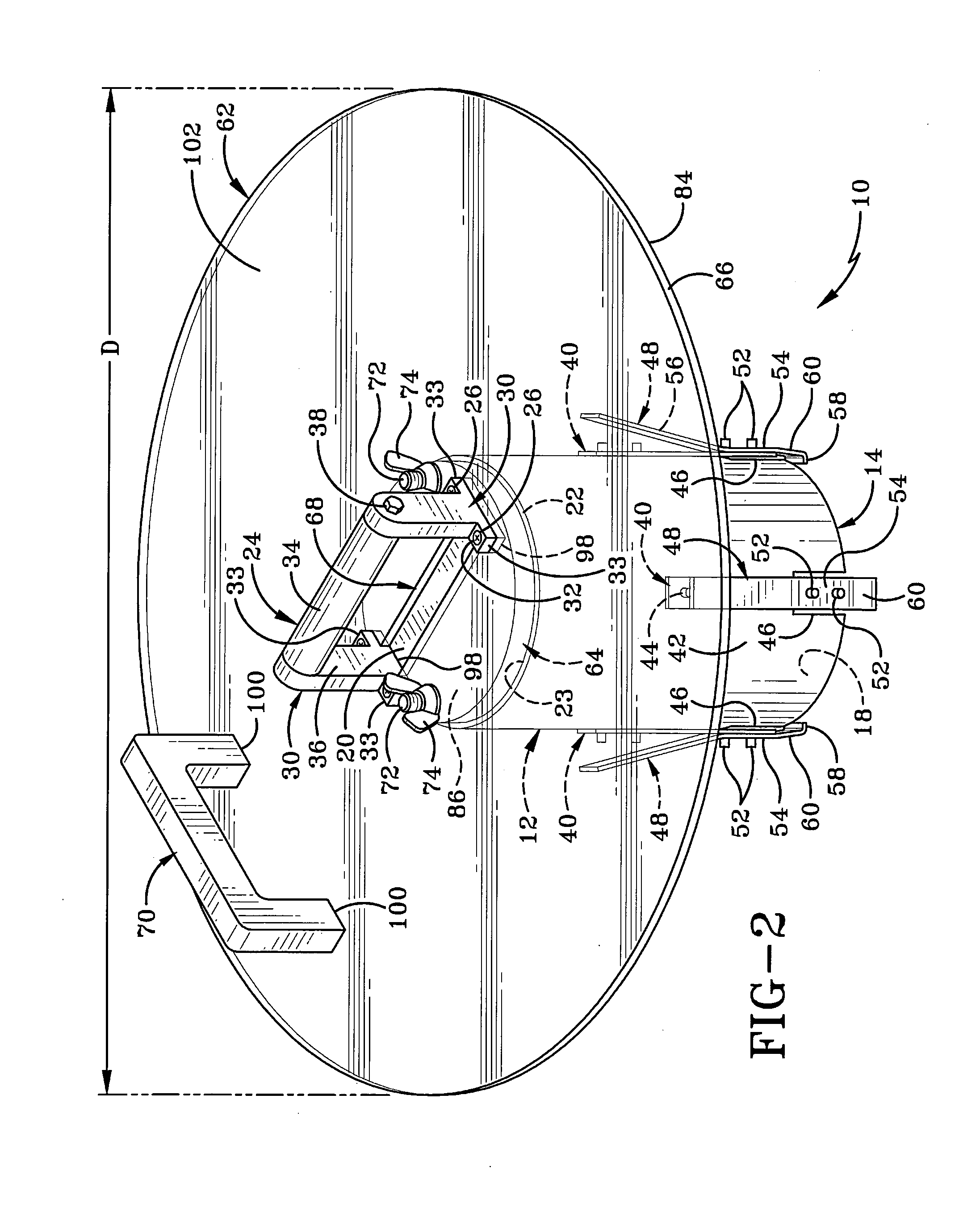
The present invention provides a tool for removing and installing an electrical power meter. The tool includes a sleeve member with hooks for engaging the meter, an attaching hook, and a handle for easy handling. A shield can be secured to the tool for added safety. The tool is designed to facilitate the safe and efficient removal of electrical power meters.

Problems solved by technology

The electrical meters can be removed by hand but there is a great deal of danger due to the high current, risk of electrocution, and electrical arc explosion that creates arc thermal energy and a pressure wave and fragmentation.
While the apparatus includes a handle proximate the back end of the tool, the tool does not protect the user from electrocution or explosion which may occur at the connection between the power meter and the distribution box when the meter is removed.

Method used


Image

  • Meter puller with safety shield
  • Meter puller with safety shield
  • Meter puller with safety shield

Examples


second embodiment

[0061]In the present invention, an enhanced meter puller 101 is shown in FIGS. 10-21, and described hereinafter.

[0062]As shown in FIGS. 10 and 14, enhanced meter puller 101 includes a meter puller 103, which may be embodied by any common off-the-shelf meter puller.

[0063]Shown particularly in FIG. 10, meter puller 103 includes a sleeve member 112 which extends from a first end 114 to a second end 116. First end 114 defines an opening 118, while a top surface 120 is disposed at second end 116. A pair of posts 130 extends outwardly away from top surface 120 and receive a central rod 134 therebetween to form a handle 124. Sleeve member 112 is comprised of a first sleeve portion 113 coupled with a second sleeve portion 115, wherein first sleeve portion 113 and second sleeve portion 115 are movable with respect to each other.

[0064]As shown in FIG. 10, meter puller 103 includes a locking mechanism or a clamping system, shown generally at 135. Clamping system 135 is intended to move first s...

third embodiment

[0080]In order to address this issue, there is shown in FIGS. 22-28, a meter puller in accordance with the present invention, generally indicated at 310. Meter puller 310 is illustrated in FIG. 22 without the presence of a shield 62 or 162 but it should be understood that a shield in accordance with the present invention could be engaged with meter puller 310 in the manner described previously herein.

[0081]Meter puller 310 is substantially similar to meter puller 103 in that it includes a sleeve member 312 comprised of a first sleeve portion 313 and a second sleeve portion 315, and has a first end 314 and a second end 316. In one embodiment of the device, meter puller 310 may be manufactured from a transparent material so that the operator is able to more accurately determine whether meter puller 310 is correctly positioned to capture meter 326 therein. As with the second embodiment, first and second sleeve portions 313, 315 are movable relative to each other. First and second sleev...


PUM

PropertyMeasurementUnit
Massaaaaaaaaaa
Lengthaaaaaaaaaa
Angleaaaaaaaaaa

Abstract

A tool for installing and removing an electrical power meter including a sleeve member defining a cavity therein with an opening to the cavity defined in the sleeve member's first end. An adjustment mechanism on the sleeve member is movable between a first position where the opening is enlarged to permit entry of a portion of the meter into the cavity; and a second position where the opening is reduced. An engagement assembly at the first end of the sleeve member grippingly engages the meter when the adjustment assembly is in the second position. The engagement assembly includes a pair of locking lips which each receive part of a peripheral edge of the meter's base therein. Gaps are defined between the locking lips to enable venting of any electrical discharge therethrough. A removable shield may be secured to the second end of the sleeve member.

Description

CROSS-REFERENCE TO RELATED APPLICATION[0001]This application is a Continuation-in-Part of U.S. patent application Ser. No. 13 / 354,034, filed Jan. 19, 2012 which is a Continuation-in-Part of U.S. patent application Ser. No. 12 / 779,577, filed May 13, 2010; the entire specifications of which are incorporated herein by reference.BACKGROUND OF THE INVENTION[0002]1. Technical Field[0003]The invention relates generally to a tool for installing and removing electrical power meters. More particularly, the invention relates to a tool with a shield for removing electrical power meters. Specifically, the invention relates to a tool with a removable shield that can be used to protect a user while installing and removing electrical power meters and where the tool includes a mechanism for opening and closing an opening to a cavity into which the meter is received; and an engagement assembly which engages a base region of the meter to retain it within the tool's cavity.[0004]2. Background Informati...

Claims


Application Information

Patent Timeline
IPC IPC(8): H05K13/04G01R1/04
CPCB25B9/00B25B27/00Y10T29/53909B25B27/14B25B27/02G01R3/00
Inventor STILLWAGON, JAMES R.
Owner KILVERT
Why Eureka
Try Eureka