Lockable safety shield assembly for a prefillable syringe

a safety shield and pre-fillable technology, which is applied in the direction of intravenous devices, infusion needles, other medical devices, etc., can solve the problems of difficult assembly of the plastic collar element onto the syringe barrel, general health risks, etc., and achieve the effect of convenient distal end covering, and convenient activation

Inactive Publication Date: 2001-02-27
BECTON DICKINSON & CO
View PDF93 Cites 91 Cited by
  • Summary
  • Abstract
  • Description
  • Claims
  • Application Information

AI Technical Summary

Benefits of technology

A lockable safety shield assembly for prefillable syringes is provided. The lockable safety shield is designed to facilitate a pharmaceutical manufacturer's assembly of the various components associated with the lockable safety shield onto the syringe in conjunction with how the syringes are normally processed by the pharmaceutical manufacturer

Problems solved by technology

More typically the case with pointed needle cannulae, accidental needle sticks that occur after the needle cannula has been used generally pose a greater health risk.
Moreover, most of the prior art approaches focus their efforts on employing a plastic collar element

Method used


Image

  • Lockable safety shield assembly for a prefillable syringe
  • Lockable safety shield assembly for a prefillable syringe
  • Lockable safety shield assembly for a prefillable syringe

Examples


Embodiment Construction

A convention utilized throughout this description is that the term "distal" refers to the direction furthest from a practitioner, while the term "proximal" refers to the direction closest to a practitioner.

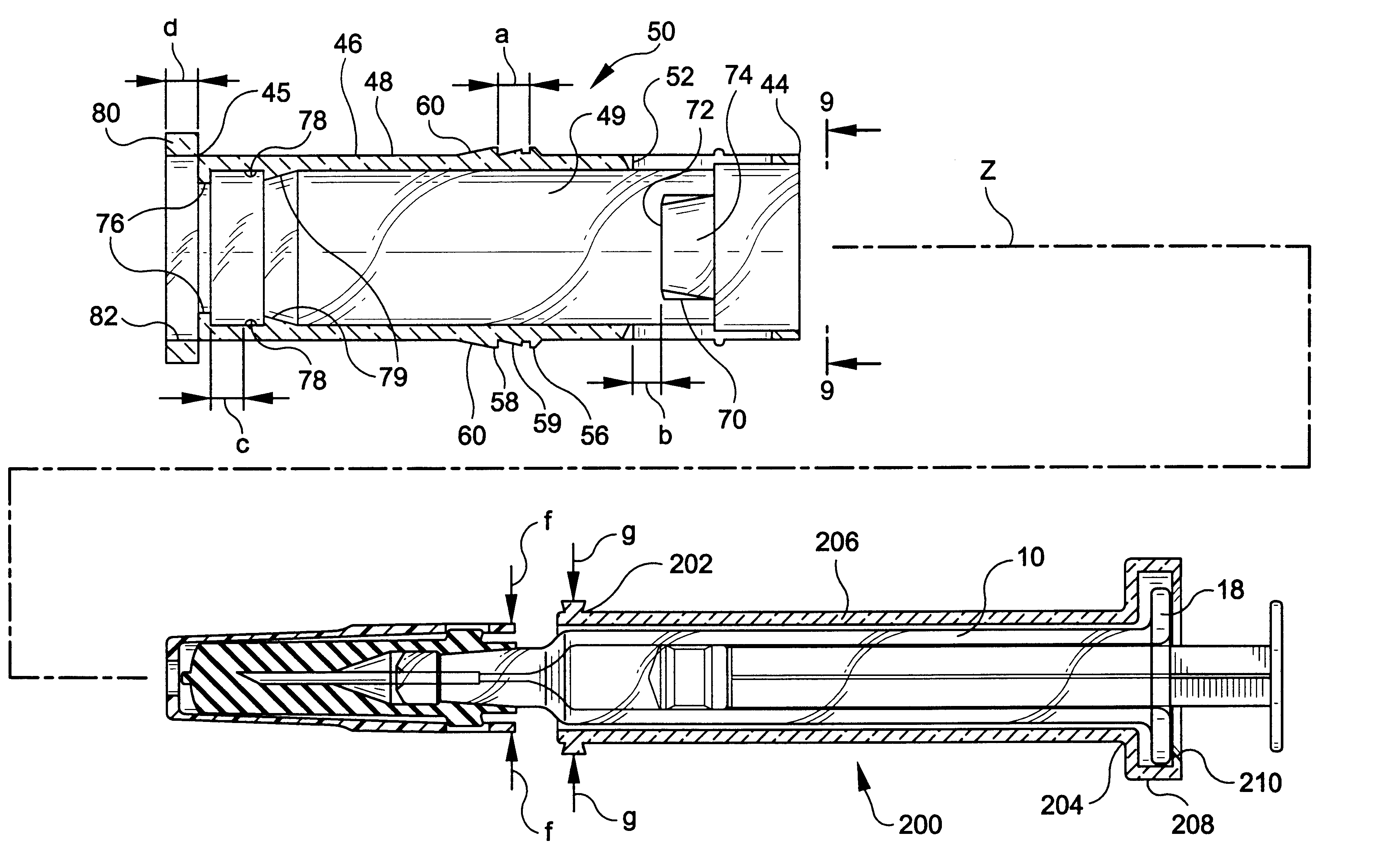
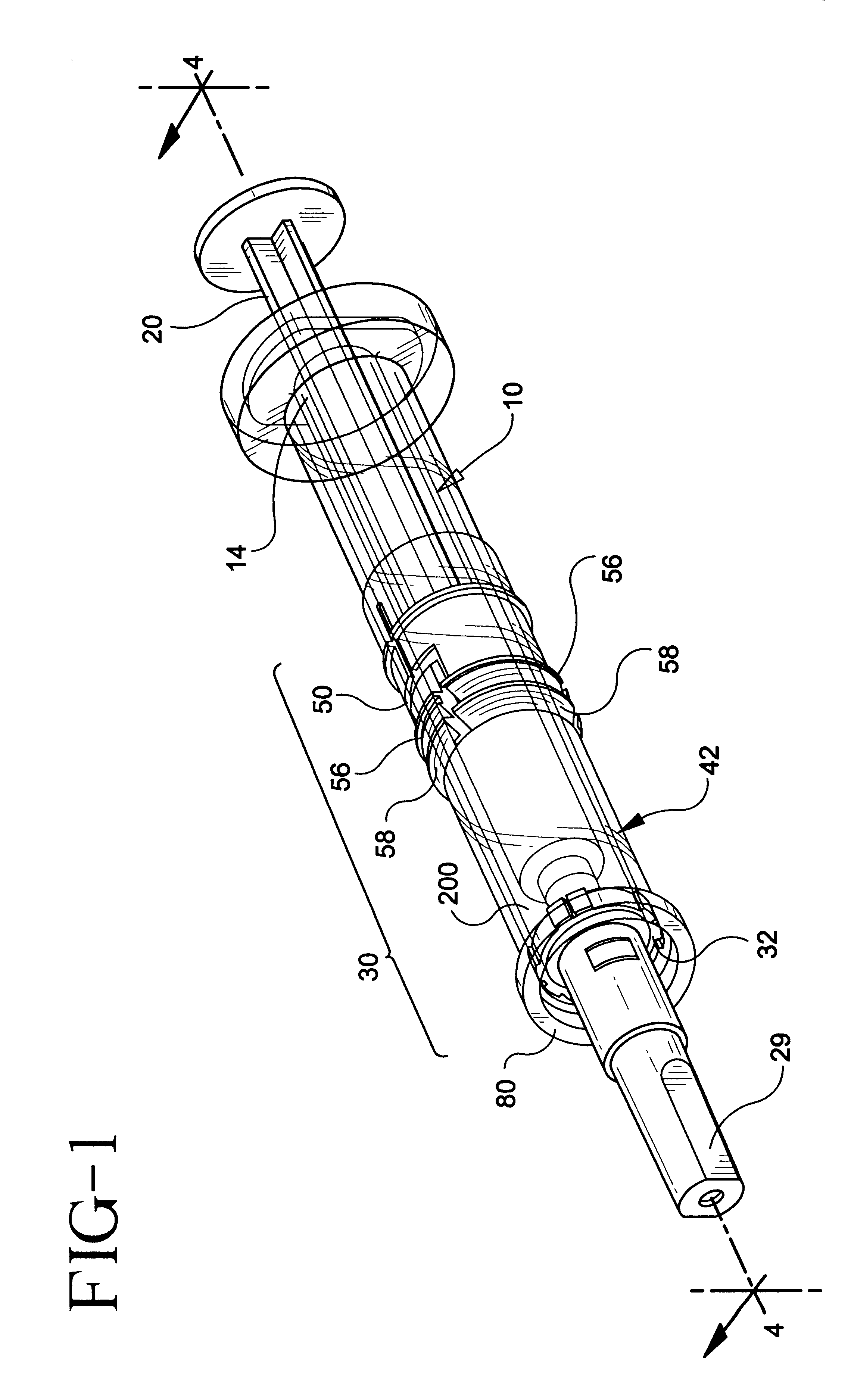
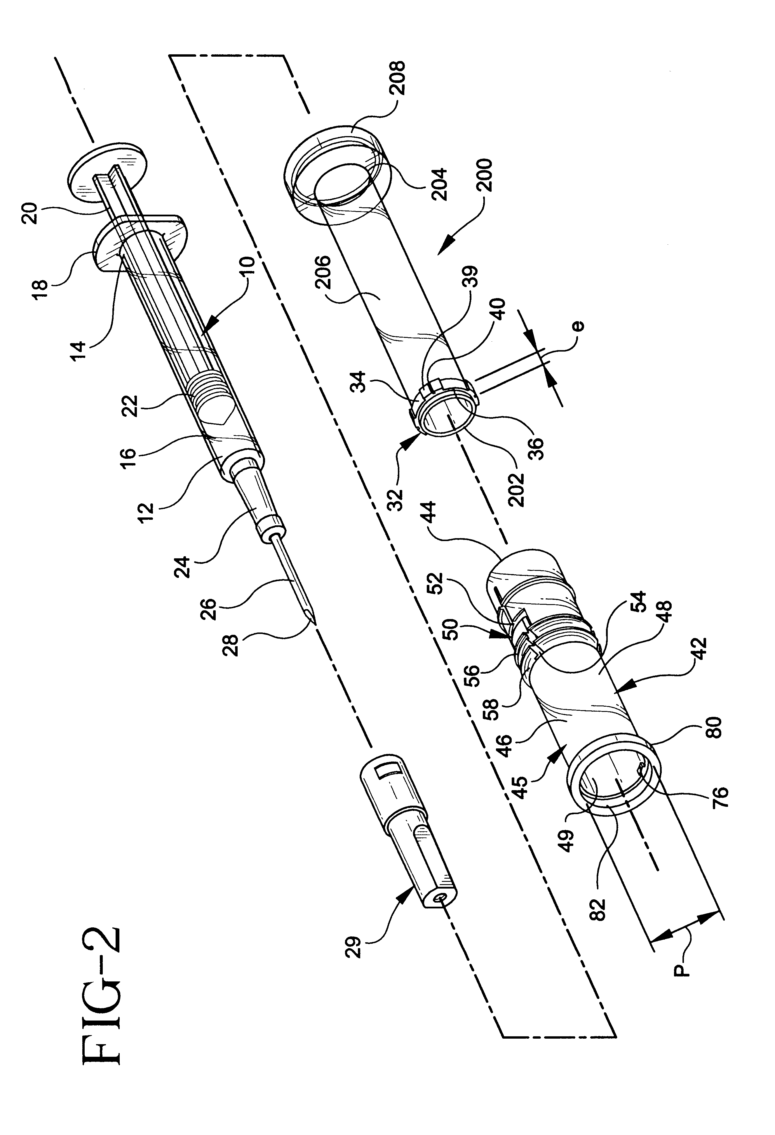
Turning now to the drawings, wherein like numerals denote like components, FIGS. 1-4 depict one embodiment of a lockable safety shield assembly 30 in accordance with the present invention. The lockable safety shield assembly 30 in accordance with the present invention can be provided in conjunction with a prefillable syringe 10. As illustrated in FIGS. 1 and 2, prefillable syringe 10 includes a barrel 16 characterized by a proximal end 14, a distal end 12, and a hub 24 provided adjacent the distal end. A flange 18 may be provided about the proximal end, with a plunger rod 20 inserted through proximal end 14. Plunger rod 20 is attached to a stopper 22 used for urging fluid through barrel 16. Fluid is emitted or aspirated via a fluid path, structured at distal end 12 of the syringe,...


PUM


Abstract

A lockable safety shield assembly for a prefillable syringe is provided. The design of the lockable safety shield assembly enhances pharmaceutical manufacturers' ease of assembling the various components as part of its filling or processing of the prefillable syringes in normal practice, while at the same time minimizes difficulties in mating parts made from different materials. A tube is placed around the outside surface of the syringe barrel and affixed thereto. A collar is provided on the tube adjacent the distal end of the syringe barrel. A safety shield is axially slidable over the tube between a retracted position, wherein the distal end of the piercing element associated with the prefillable syringe is exposed, and an extended position, wherein the safety shield is locked to the collar to protectively cover the distal end of the piercing element. The safety shield includes locking structure configured so that the shield can be easily fitted over the tube. The locking structure includes at least one deflectable arm provided on the body of the shield. The deflectable arm includes a proximal end deflectable towards the interior of the shield. A stop member is provided on the interior of a shield in spaced relation to the proximal end of the deflectable arm. A ring is axially slidable over the shield to deflect the arm towards the interior of the shield to activate the locking structure. The safety shield is slid distally by an end user such that the collar is lockingly retained between the stop member and the proximal end of the deflectable arm. The collar, the stop member, and the deflectable arm may be configured to provide tactile as well as audible indication of locking to the end user.

Description

I. FIELD OF THE INVENTIONThe invention relates to a lockable safety shield assembly for a prefillable syringe, and more particularly, to a lockable safety shield assembly for a prefillable syringe which is easily attached to a prefillable syringe and which can be subsequently activated by an end-user to form a locking mechanism for the shield.II. BACKGROUNDAs is known in the art, syringes are medical delivery devices utilizable to administer a medicament to a patient. Syringes are normally provided in prefillable form, wherein a set dosage of medicament can be filled into the syringe by a pharmaceutical manufacturer for distribution to the end user, or they are empty and intended to be filled by the end user from a vial or other source of medicament at the time administration of the medicament is desired.Syringes typically include a barrel portion adapted to retain the medicament. The distal end of the barrel is normally configured to mate with a conventional piercing element, such ...

Claims


Application Information

Patent Timeline
IPC IPC(8): A61M5/31A61M5/32A61M5/50
CPCA61M5/3135A61M5/3243A61M5/3202A61M5/3271A61M5/502A61M2005/3109A61M2005/3247A61M2205/581A61M2205/582
Inventor JANSEN, HUBERTIMBERT, CLAUDE
Owner BECTON DICKINSON & CO
Why Eureka
Try Eureka