Tread for a pneumatic tire

Inactive Publication Date: 2013-01-17
GEOR FRANCOIS PIERRE CHARLES GERARD +6
View PDF7 Cites 17 Cited by
  • Summary
  • Abstract
  • Description
  • Claims
  • Application Information

AI Technical Summary

Benefits of technology

[0008]The present invention seeks to provide a novel tread that is both quiet and

Problems solved by technology

However, these tires have been noisy with poor treadwear when driven at highway speeds on paved roads.
Lateral grooves may be limited, since lateral grooves may accelerate treadwear.
Voids, such as grooves, may provide traction, but a consequential loss of treadwear may result because the net-road contacting area

Method used


Image

  • Tread for a pneumatic tire
  • Tread for a pneumatic tire
  • Tread for a pneumatic tire

Examples


Embodiment Construction

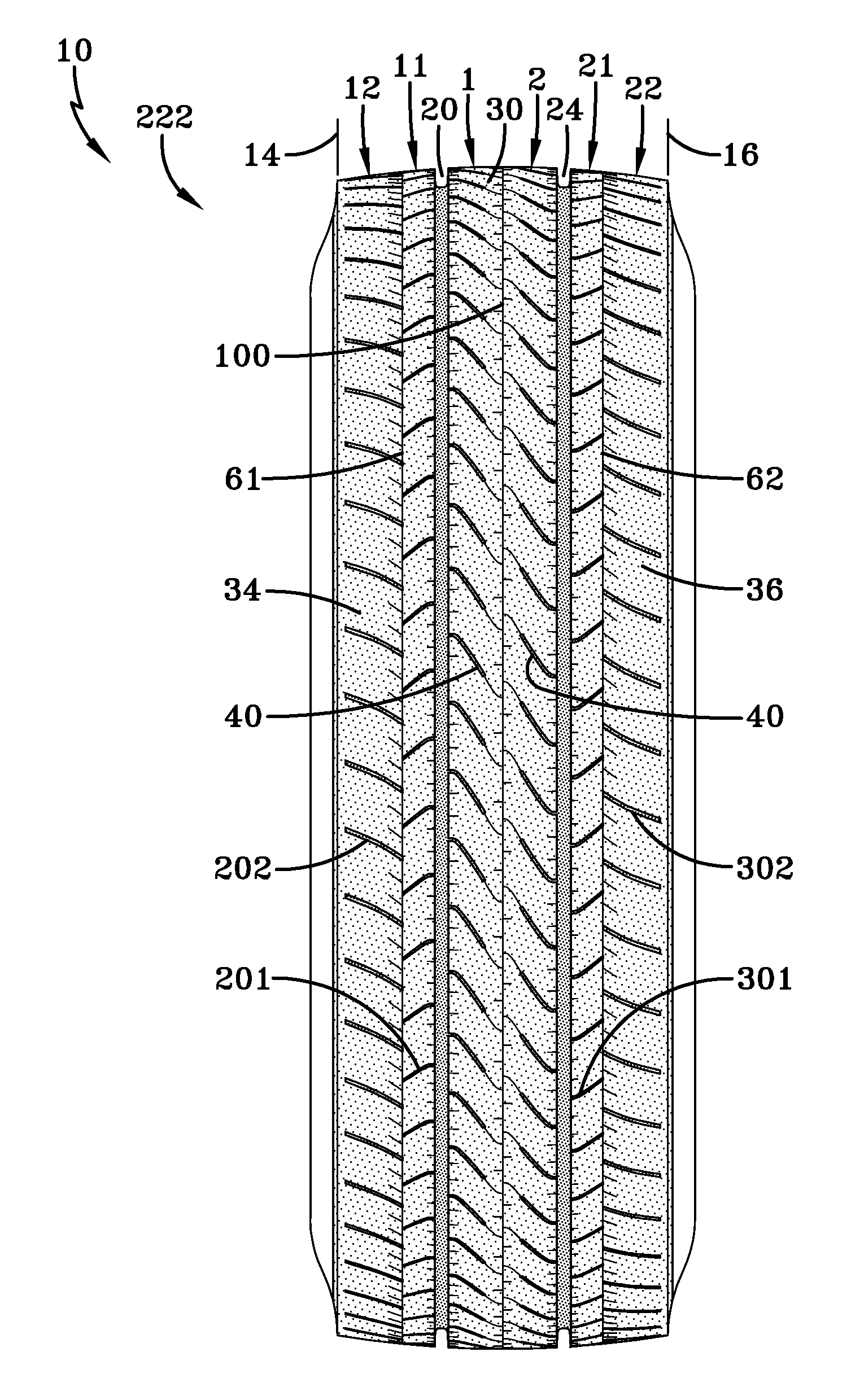
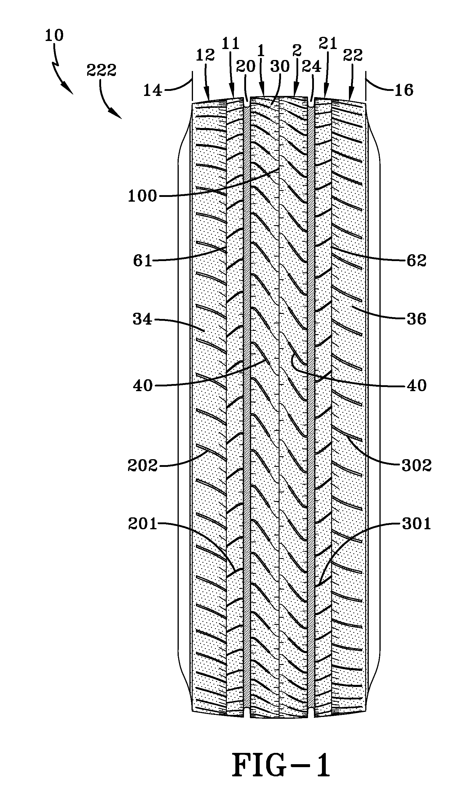
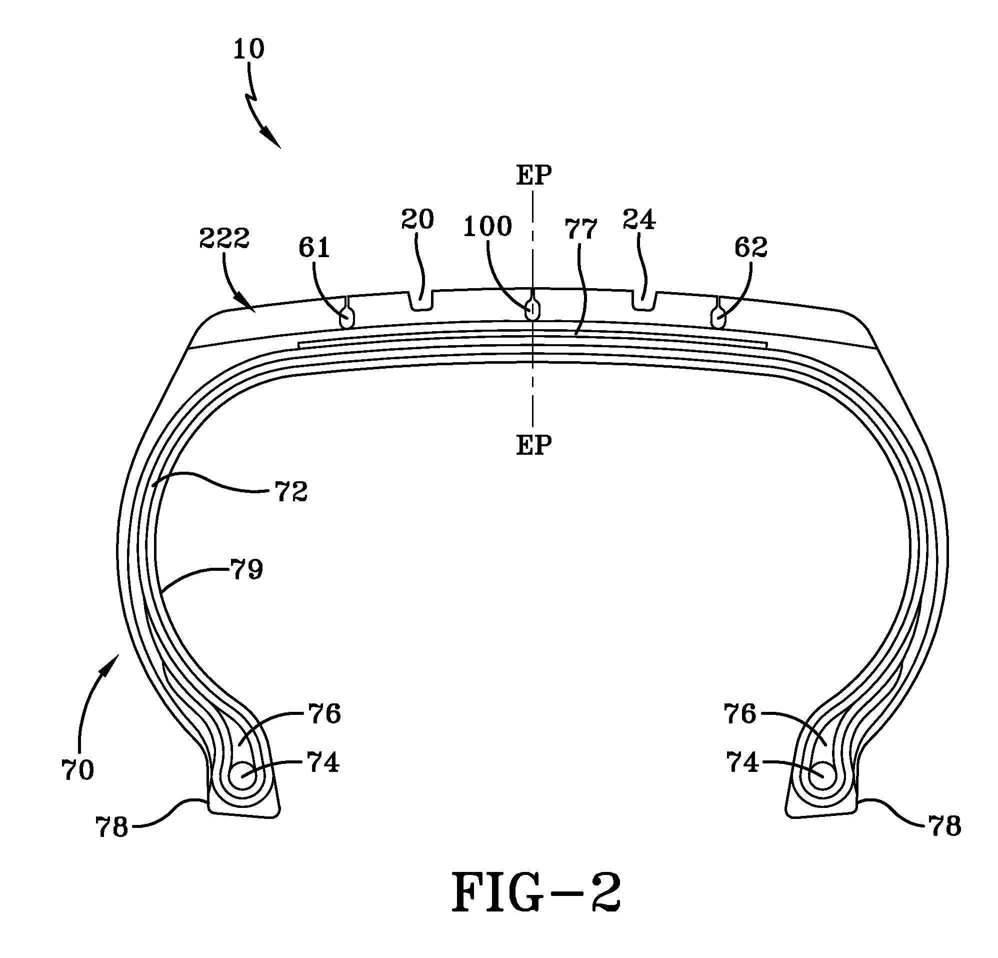
[0103]With the reference to FIGS. 1 through 4, a pneumatic tire (10) having a tread (222) according to one example of the present invention is shown. The tread (222) may have an axis of rotation R and first and second lateral edges (14, 16). The tread (222), when used with the pneumatic tire (10), may employ a tire having a carcass (70) with one or more plies (72) reinforced by radially extending synthetic or metal cords and a pair of substantially inextensible bead cores (74), an apex (76) radially above the bead cores (74), and a belt reinforcing structure (77) radially outward of the plies (72). The tire (10) may have an air impervious halobutyl liner (79) and a pair of rubber chafers (78).

[0104]While the carcass (70) and other structures contribute much to the performance of the pneumatic tire (10), the example tread (222) of FIG. 1 may have two circumferentially continuous grooves (20, 24). Interposed between the two circumferentially continuous grooves may be a central rib (30...


PUM


Abstract

A tread for a pneumatic tire includes a first circumferentially continuous groove, a second circumferentially continuous groove, a central rib interposed between the two circumferentially continuous grooves and extending continuously around a circumference of the tread, a first circumferentially extending shoulder rib disposed laterally outside of the first circumferentially continuous groove, and a second circumferentially extending shoulder rib disposed laterally outside of the second circumferentially continuous groove. The central rib has a plurality of circumferentially spaced sipes arranged in a first circumferential row and a second circumferential row. The sipes of the first row originate at the first circumferentially continuous groove and the sipes of the second row originate at the second circumferentially continuous groove. The sipes of both the first and second rows extend axially inward to a circumferentially extending and continuous variable center groove. The variable center groove has a minimum circumferentially extending opening at a radially outermost portion. As the tread wears and the radially outermost portion of the tread moves radially inward, the circumferentially extending opening of the variable center groove widens to a maximum circumferentially extending opening greater than the minimum circumferentially extending opening.

Description

TECHNICAL FIELD[0001]The present invention relates to a pneumatic tire, and more particularly, to a tread for a pneumatic tire.BACKGROUND ART[0002]Pneumatic truck tires constructed for slippery or even winter driving conditions are intended to be suitable for running on surfaces of reduced compactness such as snow-covered roadways. Such tires are required to demonstrate suitable traction (gripping), power, braking, and handling characteristics on wet or snow covered surfaces while maintaining rolling resistance and mileage performance. The tread pattern of commercial truck tires must accordingly meet such competing objectives in order to provide the user with acceptable tire performance.[0003]With the continuing rise in popularity of light trucks and cargo vans, there exists a need to provide tires that have the ability to be driven on paved roads while carrying heavy loads without excessive noise, yet also to be capable of being driven in heavy snow or wet roads. Often these tires ...

Claims


Application Information

Patent Timeline
IPC IPC(8): B60C11/12
CPCB60C11/04B60C11/0306B60C11/1204B60C11/0323B60C2011/1209B60C11/1281
Inventor GEORGES, FRANCOIS PIERRE CHARLES GERARDWINKIN, DIDIERBRAUN, LOTHARSEVERENS, FRANK PIERREGEORGES, CLAUDE PIERREMATHONET, VINCENT BENOITSCHEUREN, DANIEL
Owner GEOR FRANCOIS PIERRE CHARLES GERARD
Why Eureka
Try Eureka