

Method of fabricating holographic contact lens
a holographic contact lens and lens body technology, applied in the field of holographic contact lens manufacturing, can solve the problems of permanent impairment of eyesight and visibility, eye injuries, eye damage, etc., and achieve the effect of being easier to wear for long hours
- Summary
- Abstract
- Description
- Claims
- Application Information
AI Technical Summary
Benefits of technology
Problems solved by technology
Method used
Image

Examples
first embodiment
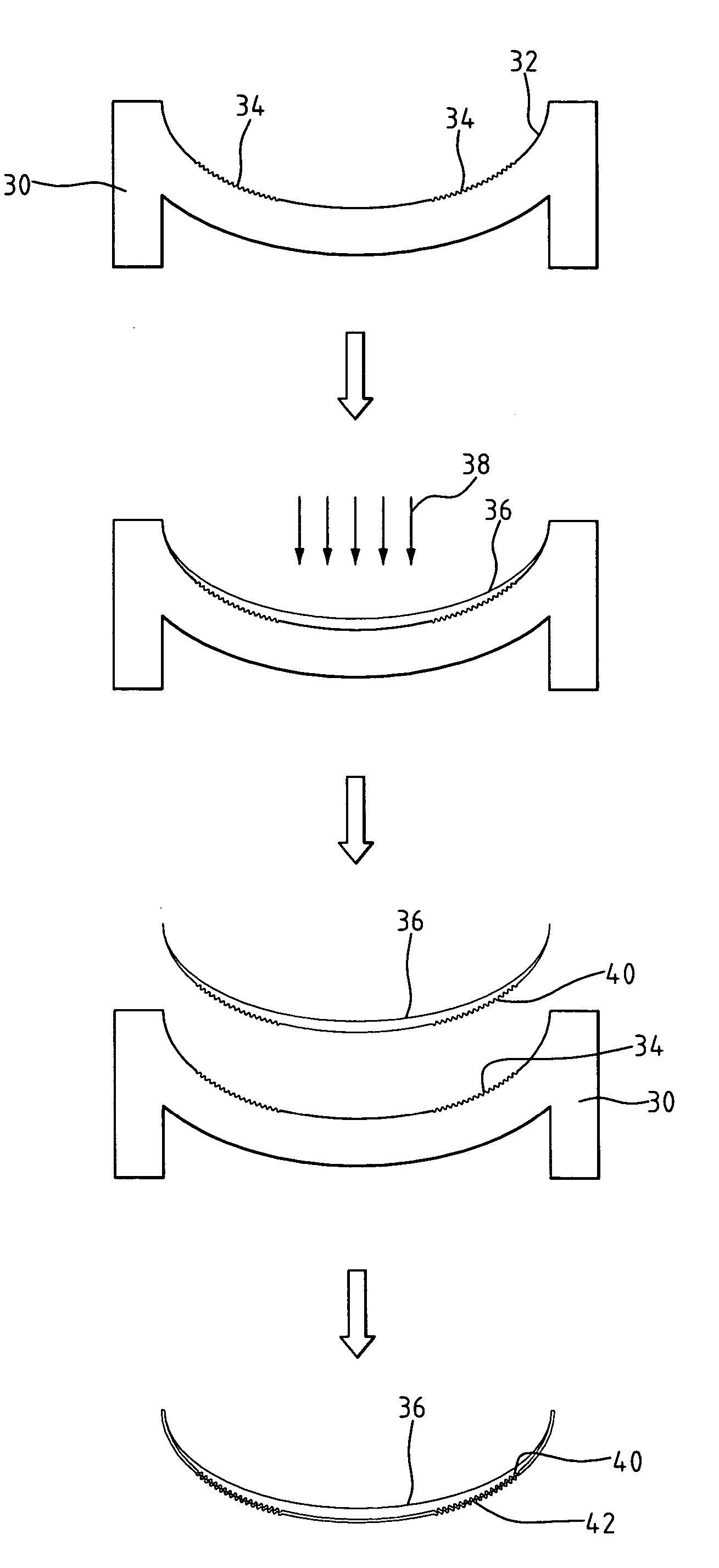
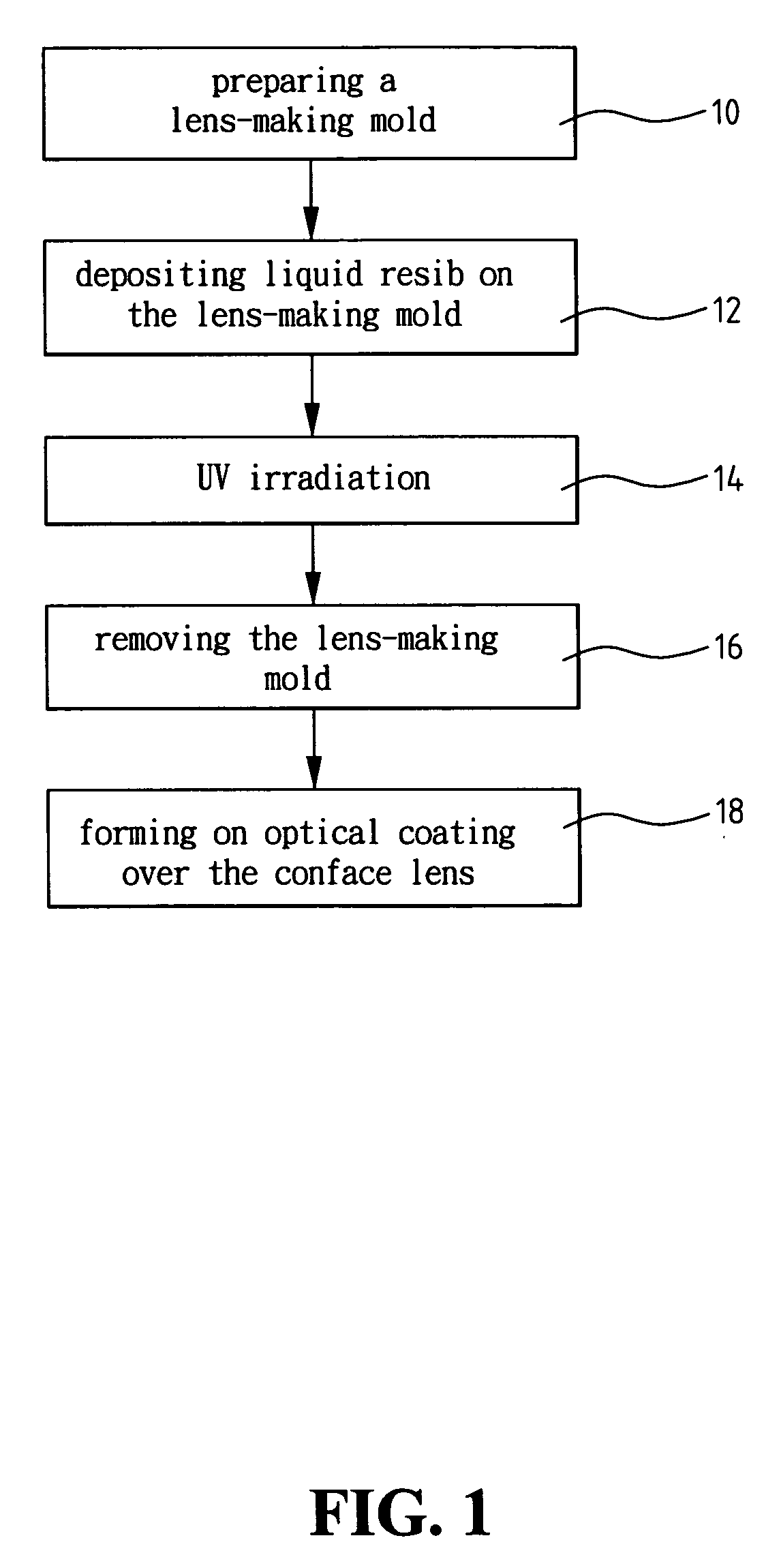
[0045] Case 1: Referring to FIG. 3, the fabrication of the holographic contact lens, as the invention demonstrates, is accomplished by a conventional spin casting technique. The sequence of fabrication steps includes: [0046] (a) preparing a lens-making mold 30 having multiple micro-lines 34 imprinted on the inward curving portion of the inner wall 32 of the mold 30; and then [0047] (b) spreading liquid resin along the inner wall 32 of the lens-making mold 30, where spin casting technique is employed to spread the liquid resin evenly over the lens-making mold 30 and to shape the resin layer; [0048] (c) casting an UV ray 38 on the resin layer to cause the resin to solidify under the UV irradiation and to develop into the shape of a contact lens 36; [0049] (d) removing the lens-making mold 30 after the contact lens 36 has been completely solidified, where the micro-lines 34 on the lens-making mold 30 have been successfully copied onto the corresponding light interference zone 40 on the...
case 2
[0051] Referring to FIG. 4, the fabrication of the holographic contact lens, as the second preferred embodiment of the invention demonstrates, is accomplished by a cast molding technique. The sequence of fabrication steps includes: [0052] (a) preparing a lens-making mold 30 having an upper half 44 and a lower half of the mold 30, where multiple micro-lines 34 are imprinted on the inner wall on the lower half of the mold 30; [0053] (b) depositing liquid resin (not shown in diagram) along the inner wall 32 in the cavity between the lower and upper halves of the lens-making mold 30, where the conventional cast molding is used to shape the resin layer with the aid of the upper half 44 of the mold 30 by squeezing the liquid resin to make the resin spread out evenly over the lower half of the mold 30; [0054] (c) casting an UV ray 38 to cause the resin layer to solidify under the UV irradiation and develop into the shape of a contact lens 36; [0055] (d) removing the lens-making mold 30 to...
third embodiment
[0057] Case 3: Referring to FIG. 5, the fabrication of the holographic contact lens, as the invention demonstrates, is accomplished by a conventional cast molding technique. The sequence of fabrication steps includes: [0058] (a) preparing a lens-making mold 30 having an upper half 44 and a lower half of the mold 30, where multiple micro-lines 34 are imprinted on the inner wall of the upper half of the mold 30; [0059] (b) depositing liquid resin along the inner wall 32 in the cavity between the lower and upper halves 44 of the lens-making mold 30, where the conventional cast molding technique is used with the aid of the upper half 44 to shape the resin layer by squeezing the liquid resin to make the resin spread out evenly over the lower half of the lens-making mold 30; [0060] (c) casting an UV ray 38 on the resin layer to cause the resin to solidify under the UV irradiation and to develop into the shape of a contact lens 36; [0061] (d) removing the lens-making mold 30 and retrieving...
PUM
| Property | Measurement | Unit |
|---|---|---|
| width | aaaaa | aaaaa |
| thickness | aaaaa | aaaaa |
| diameter | aaaaa | aaaaa |
Abstract
Description
Claims
Application Information