
Switch unit, and related method

a technology of switch unit and switch body, which is applied in the direction of switch power arrangement, emergency power supply arrangement, transportation and packaging, etc., can solve the problems of inability of electronic board to drive the contactor, the use and functioning of known medium voltage panels are limited, and the external power supply of electronic boards is not reliabl

Active Publication Date: 2013-01-17
ABB (SCHWEIZ) AG
View PDF16 Cites 8 Cited by
  • Summary
  • Abstract
  • Description
  • Claims
  • Application Information

AI Technical Summary

Benefits of technology

The patent describes a switch unit that can monitor the main power supply and quickly enter a low-consumption mode when there is no power. When an opening command is needed, the switch unit can quickly reactivate only the necessary devices to perform the commanded action. This allows for quicker and more efficient response times in situations where there is no external power supply. The technical effect of this invention is a more reliable and efficient switch that can quickly and easily initiate a low-consumption mode when power is not available.

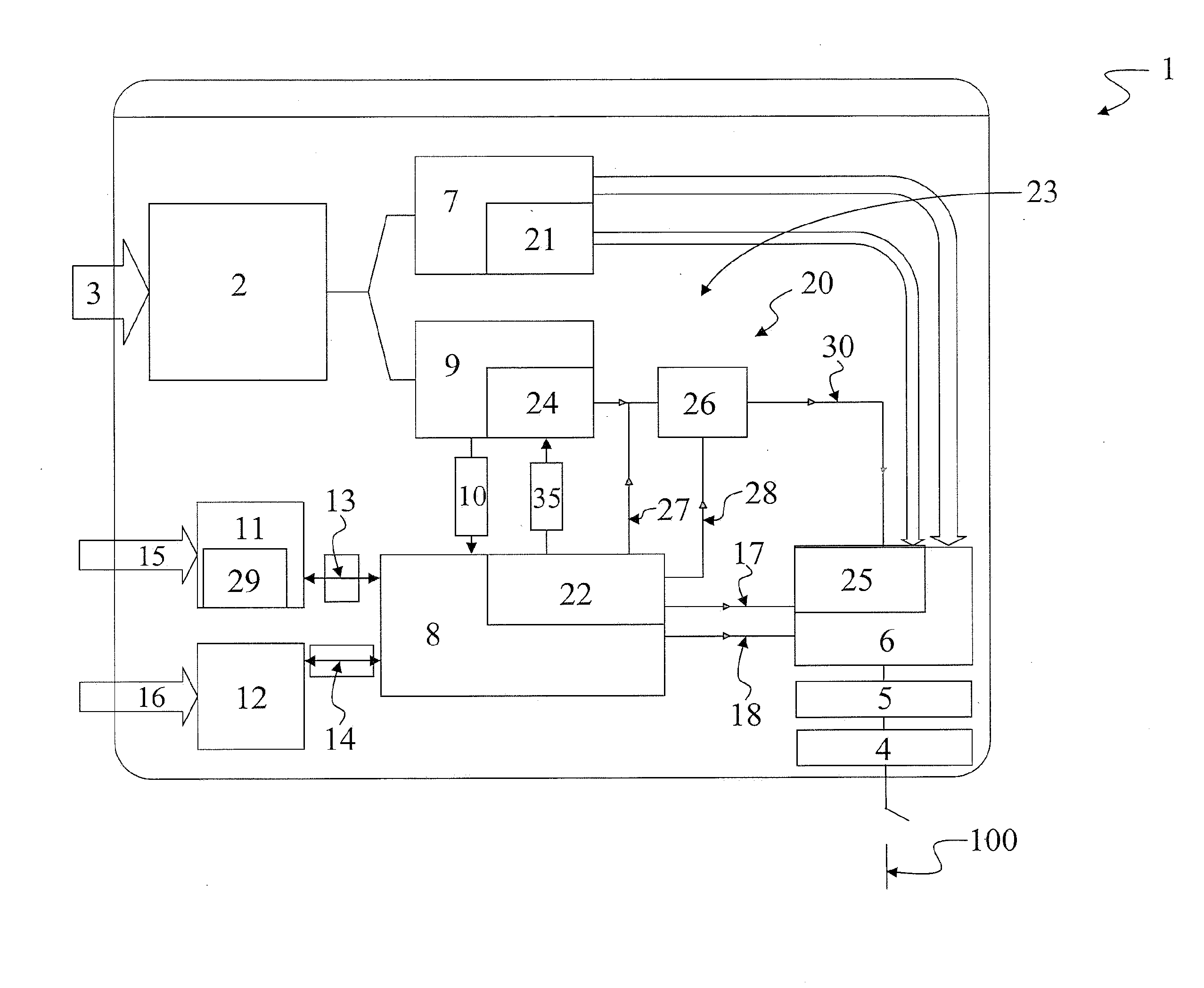
Problems solved by technology

However, known medium voltage panels are limited in their use and functioning in critical situations.
For example, in case of a lack of external main power, due for example to faults or failures of the industrial plant in which the panel is installed, the electronic board is not electrically supplied by the external power mains.
As a result, the electronic board is not able to drive the contactor in order to open the electric circuit.
Consequently, the integrity of such downstream devices, or of other devices connected to the panel, are not safely preserved, and may be jeopardized by possible damaging events that affect the panel or an overall system in which the panel is included.

Method used


Image

  • Switch unit, and related method
  • Switch unit, and related method
  • Switch unit, and related method

Examples


Embodiment Construction

[0014]Exemplary embodiments of the present disclosure provide improvements to known medium voltage panels. Exemplary embodiments of the present disclosure provide a switch unit, which can be associated with a medium voltage panel, and which is able to reliably operate in critical conditions, such as in case of a lack or drop of external main power supply due, for example, to a fault or failure of the plant to which the switch unit is connected.

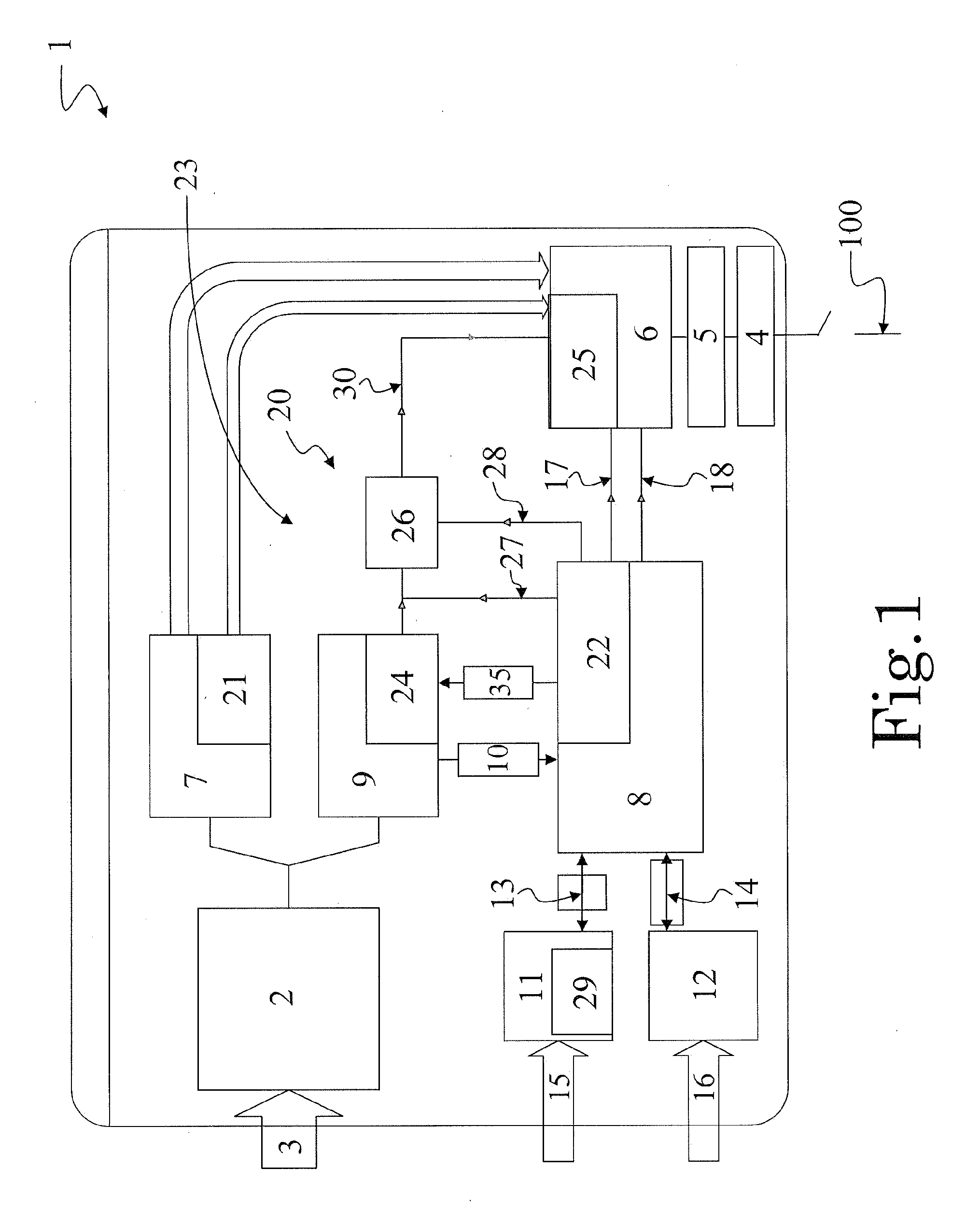
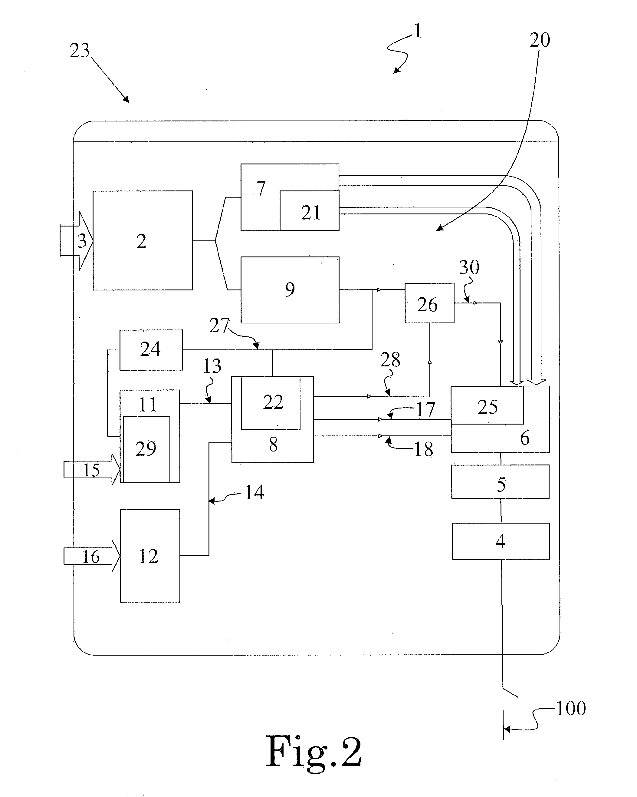
[0015]An exemplary embodiment of the present disclosure provides a switch unit which includes a current switching device drivable by an electromagnetic actuator for opening / closing an electric circuit associated with the switch unit, and a first energy storage means for storing an amount of electric energy for the electromagnetic actuator. The exemplary switch unit also includes electronic controller means for controlling a supply of the amount of electric energy from the energy storage means to the electromagnetic actuator. The electronic con...


PUM


Abstract

A switch unit includes a current switching device drivable by an electromagnetic actuator for opening / closing an electric circuit associated with the switch unit, a first energy storage for storing electric energy for the electromagnetic actuator, and electronic controller means which are supplied by an external power line and control a supply of the electric energy from the energy storage means to the electromagnetic actuator. The switch unit includes emergency procedure operating means associated with the electronic controller means and provided with a second energy storage means. The emergency procedure operating means are configured for enabling driving of the current switching device and opening the associated electric circuit in an emergency condition in which a lack or drop or irregular supply of the external power line is experienced.

Description

RELATED APPLICATIONS[0001]This application claims priority as a continuation application under 35 U.S.C. §120 to PCT / EP2011 / 053391, which was filed as an International Application on Mar. 7, 2011 designating the U.S., and which claims priority to European Application 10156853.3 filed in Europe on Mar. 18, 2010. The entire contents of these applications are hereby incorporated by reference in their entireties.FIELD[0002]The present disclosure relates to a switch unit that is able to reliably perform switching operations in conditions such as a power main drop or lack of power due to plant faults or failures etc. The switch unit according to the present disclosure effectively safeguards end user devices or electric appliances / apparatuses which are operatively connected thereto. The switch unit of the present disclosure is suitable to be used in medium voltage panels or switchboards or other medium voltage appliances.BACKGROUND INFORMATION[0003]As used herein, the phrase “medium voltag...

Claims


Application Information

Patent Timeline
Patent Type & Authority Applications(United States)
IPC IPC(8): H02J9/00
CPCH01H9/54H01H3/28
Inventor USAI, ROBERTOMANNINO, FABIO
Owner ABB (SCHWEIZ) AG
Learn More