
Control apparatus incorporating a voltage converter for controlling lighting apparatus

a technology of voltage converter and control apparatus, which is applied in the direction of electrical equipment, discharge tube electric supplies, welding electric supplies, etc., can solve the problems of increased cost and difficulty in source, difficulty in obtaining, and difficulty in obtaining constant voltage power supplies with adjustable output, etc., to achieve increased resolution, increase resolution, and increase resolution

Active Publication Date: 2013-01-17
ARKALUMEN
View PDF13 Cites 60 Cited by
  • Summary
  • Abstract
  • Description
  • Claims
  • Application Information

AI Technical Summary

Benefits of technology

The invention provides a control apparatus for a lighting apparatus that can adjust the output voltage based on a voltage control signal. The control apparatus includes a voltage converter and a control module. The control module sets the duty cycle of the voltage control signal for different parts of a fine control period. By doing this, the control apparatus can achieve an increased resolution in controlling the output voltage from the voltage converter. This allows for more precise and accurate control of the lighting apparatus.

Problems solved by technology

However, constant voltage power supplies having an adjustable output are more expensive and difficult to source compared to constant voltage power supplies having a fixed output voltage.
However, complications may arise as a result of LEDs having different forward voltages as a result of manufacturing tolerances or otherwise having different characteristics.
Discrepancies in the forward voltages of the LEDs may be problematic when various LED channels are connected in parallel.
Certain other known LED architectures that utilize pulse-width modulation (PWM) may result in relatively large current fluctuations that may increase as the total current through the LEDs increases.
However, the control architecture in Melanson is limited and does not permit aspects of the light output, such as the color or color temperature, to be varied.
This architecture may be relatively complex and result in large current fluctuations in the current drawn from the power supply.
Certain other existing control systems for lighting apparatus utilizing a voltage converter may also have limited resolution to control the output voltage from the voltage converter.
Additionally, the relationship between various control signals used in the lighting apparatus may contribute to a visible flicker of the light output from the lighting apparatus under certain operation conditions.

Method used


Image

  • Control apparatus incorporating a voltage converter for controlling lighting apparatus
  • Control apparatus incorporating a voltage converter for controlling lighting apparatus
  • Control apparatus incorporating a voltage converter for controlling lighting apparatus

Examples


Embodiment Construction

[0038]In LED lighting architectures employing constant voltage power supplies, referred to as constant voltage architectures, it is important to provide a suitable voltage to the LEDs and ensure that the current supplied does not exceed certain thresholds. As noted above, certain constant voltage power supplies have an adjustable output voltage. Other power supplies having a fixed output voltage are more readily available and economical and may be used in conjunction with a voltage converter to provide a certain output voltage to the LEDs in a lighting system.

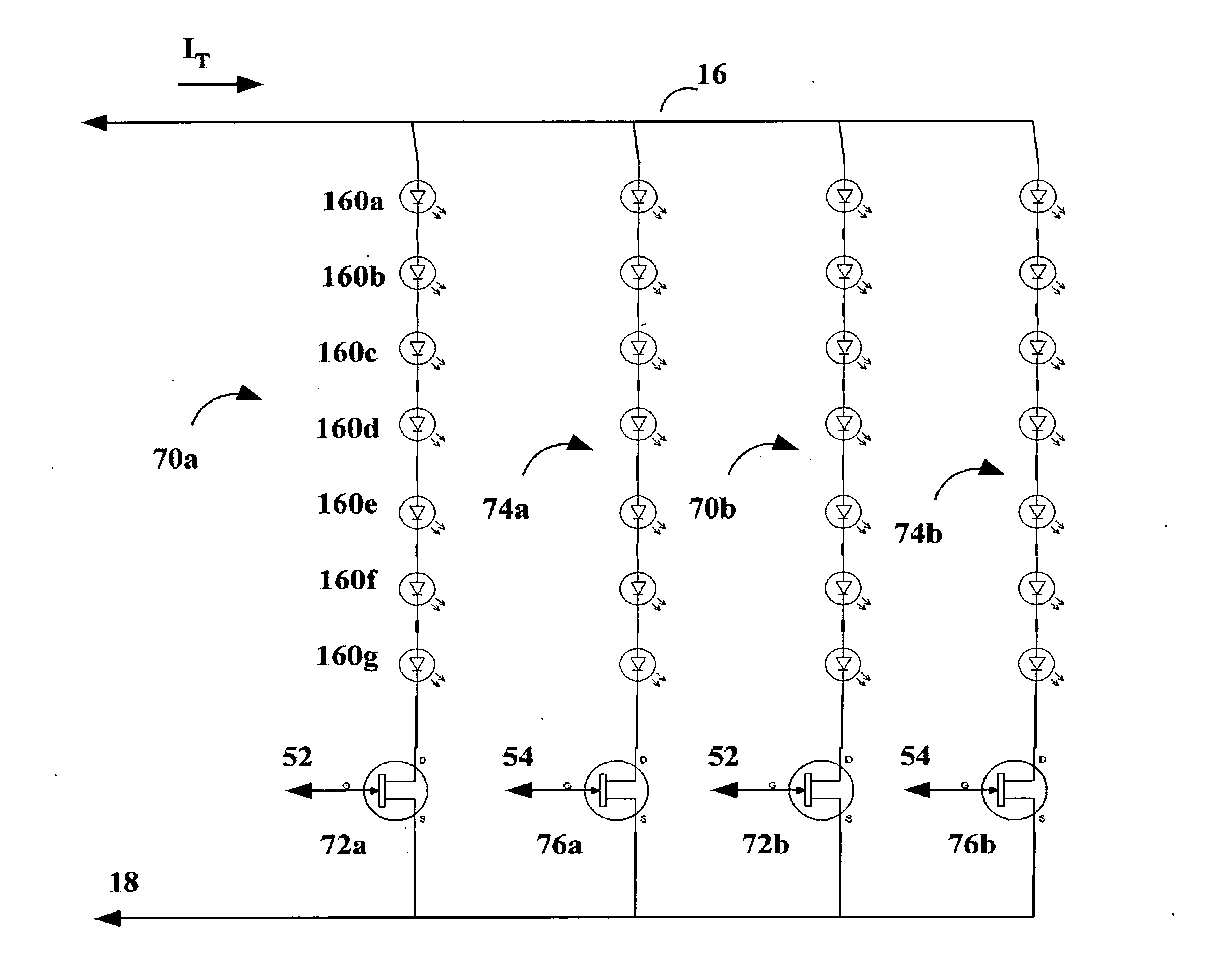
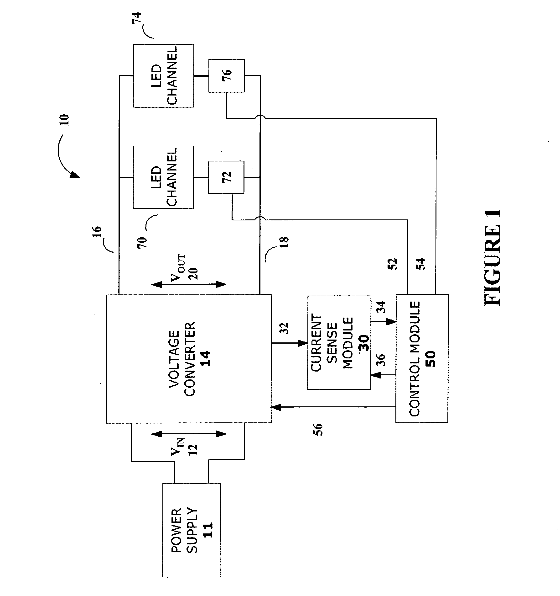
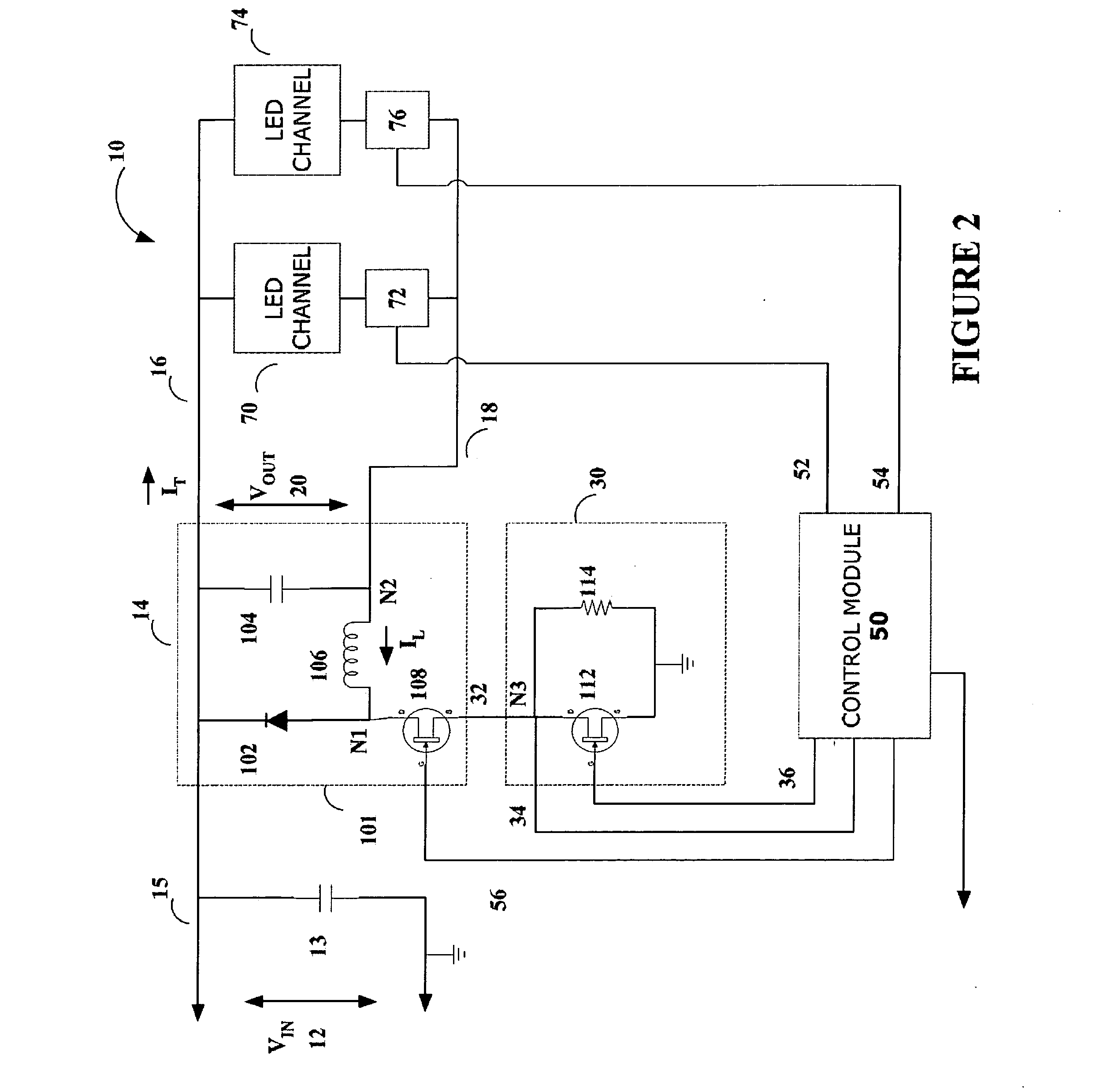
[0039]A schematic of the architecture of an embodiment of the lighting apparatus 10 is shown in FIG. 1. A power supply 11 may be coupled to a voltage converter 14 and provide an input voltage 12 to voltage converter 14. The input voltage 12 may be defined between a positive supply and a reference ground. Power supply 11 may be a constant voltage power supply having a fixed output voltage, for example, a 24V power supply. The vo...


PUM


Abstract

A lighting apparatus may comprise a voltage converter operable to supply a current to at least two LED channels coupled between a high voltage rail and a low voltage rail coupled to the voltage converter output. The LED channels may be operated to selectively allow a current to flow through them. The lighting apparatus may have a control module operable to control the total current from the voltage converter and the current through each of the LED channels. The control module may also be operable to set the respective control signals to maintain a constant total current from the voltage converter while permitting aspects of the light output including, the intensity, color, and color temperature to be set and varied. Additionally, the control module may be operable to synchronize the various control signals, obtain a representative sample of the current through the voltage converter, and operate in different modes.

Description

CROSS-REFERENCE TO RELATED APPLICATION[0001]The present application claims the benefit under 35 USC 119(e) of U.S. Provisional Patent Application No. 61 / 507,117 entitled “Dimmable LED Lighting Architecture Incorporating a Voltage Converter” by Briggs filed on Jul. 12, 2011 and hereby incorporated by reference.FIELD OF THE INVENTION[0002]The present invention relates generally to light emitting diode (LED) lighting systems, and more particularly to LED lighting systems incorporating a voltage converter.BACKGROUND OF THE INVENTION[0003]Lighting systems utilizing light emitting diodes (LEDs) are becoming increasingly popular and include systems employing constant current and constant voltage power supply architectures. Constant current systems may employ a power supply having a control system to output a desired current, within certain design parameters, irrespective of the number of LEDs attached to the power supply. In contrast, constant voltage power supply architectures require the...

Claims


Application Information

Patent Timeline
Patent Type & Authority Applications(United States)
IPC IPC(8): H05B37/02H05B44/00
CPCH05B33/0815H05B33/0827H05B37/00B23K11/248H05B41/2827H05B33/0857H05B45/46H05B45/20H05B45/3725H05B45/38H05B47/25H05B45/375H05B45/48
Inventor BRIGGS, GERALD EDWARD
Owner ARKALUMEN
Learn More