
Active compensating hydrostatic bearing and hydrostatic bearing module using the same

a technology of hydrostatic bearing and self-sensing, which is applied in the direction of sliding contact bearings, mechanical equipment, rotary machine parts, etc., can solve the problems of poor static rigidity of conventional hydrostatic bearing systems, the problem of operation delay, and the poor static rigidity of conventional capillary-type restrictors or aperture restrictors, etc., to achieve high static rigidity, good dynamic rigidity, and high precision application

Active Publication Date: 2013-01-17
NATIONAL TSING HUA UNIVERSITY
View PDF3 Cites 2 Cited by
  • Summary
  • Abstract
  • Description
  • Claims
  • Application Information

AI Technical Summary

Benefits of technology

The invention provides an active compensating hydrostatic bearing that has both high static rigidity and good dynamic rigidity, suitable for high precision applications and dynamic load variations. The bearing has a simple structure and can be easily maintained and replaced. It also has small vibration under dynamic loads and works as a vibration absorber to effectively absorb vibration between the structures. This invention solves the problem of delay in the hydrostatic bearing system and provides better stability and precision for machine tools.

Problems solved by technology

However, since the conventional hydrostatic bearing system always has the externally connected restrictor, which is connected to the pocket through an oil conduit, the delay is caused in the compensation response due to the oil conduit between the restrictor and the pocket.
Therefore, the conventional hydrostatic bearing system has the problem of operation delay.
In addition, the conventional capillary-type restrictor or aperture restrictor, for example, has the poor static rigidity because the restrictor flow resistance caused by the capillary-type restrictor is a constant and cannot be adjusted to perform the compensation according to the variation of the pocket pressure.

Method used


Image

  • Active compensating hydrostatic bearing and hydrostatic bearing module using the same
  • Active compensating hydrostatic bearing and hydrostatic bearing module using the same
  • Active compensating hydrostatic bearing and hydrostatic bearing module using the same

Examples


Embodiment Construction

[0024]The present invention will be apparent from the following detailed description, which proceeds with reference to the accompanying drawings, wherein the same references relate to the same elements.

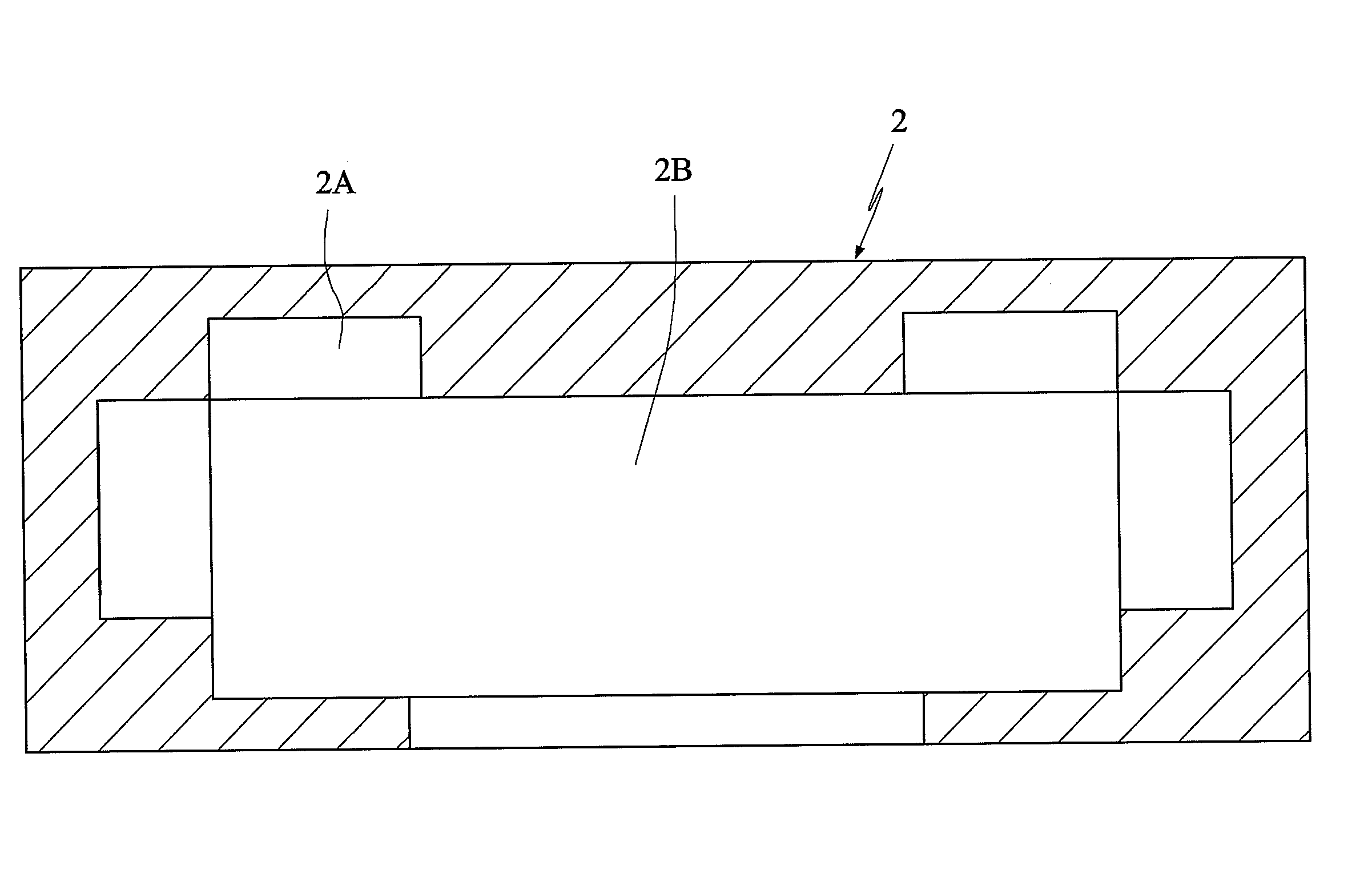
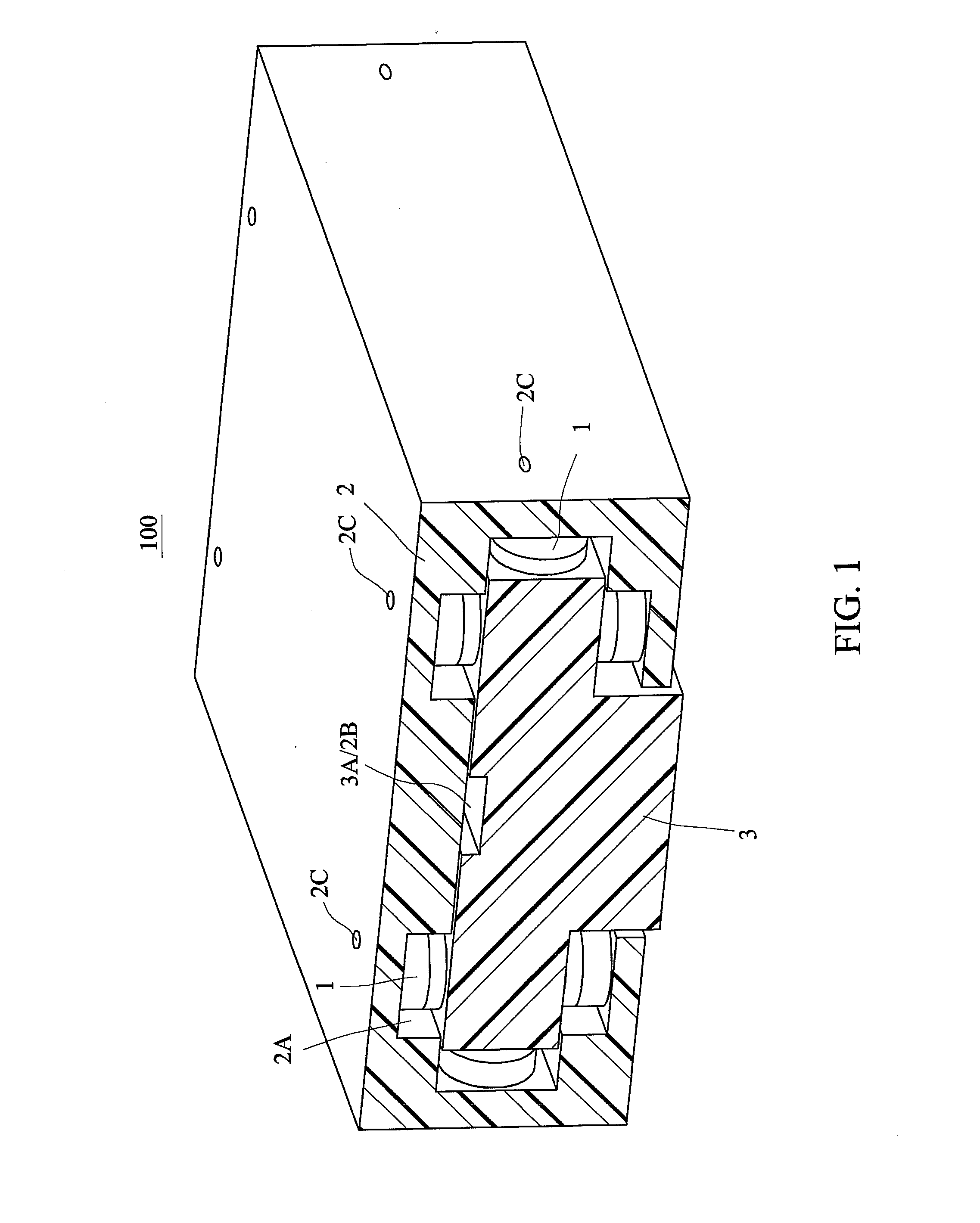
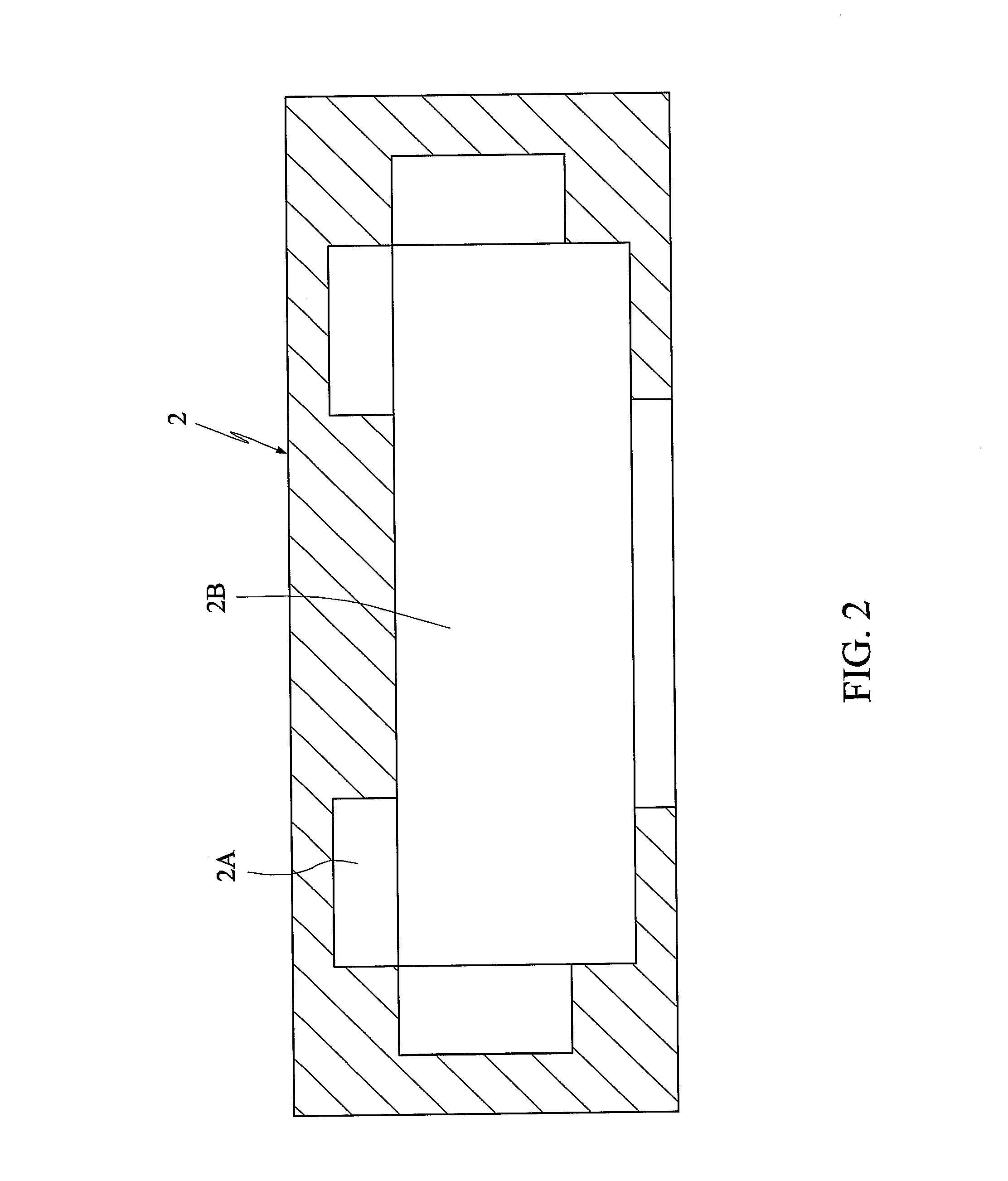
[0025]FIG. 1 is a cross-sectional view showing a hydrostatic bearing module 100 according to a preferred embodiment of the invention. FIG. 2 is a cross-sectional view showing a first structure of the hydrostatic bearing module 100 according to the preferred embodiment of the invention. Referring to FIGS. 1 and 2, the hydrostatic bearing module 100 of the invention includes a first structure 2, a second structure 3 and a plurality of active / self-sensing compensating hydrostatic bearings 1. The hydrostatic bearings 1 are disposed between the first structure 2 and the second structure 3 to allow relative movement between the first structure 2 and the second structure 3. In one example, the first structure 2 is, for example, a movable table of a machine tool, while the second structure 3 ...


PUM

PropertyMeasurementUnit
pressureaaaaaaaaaa
stabilityaaaaaaaaaa
rigidityaaaaaaaaaa

Abstract

An active / self-sensing compensating hydrostatic bearing is disposed between first and second structures to allow relative movement between the first and second structures. The hydrostatic bearing includes a body and a compensator. The body, fixed to the first structure and separated from the second structure by a first gap, has a chamber and an input passage and an output passage both communicating with the chamber. The compensator is disposed in the chamber. A compensating passage, communicating with the input passage and the output passage, is formed between the body and the compensator. A pressurized fluid flows from the input passage to the output passage through the compensating passage, and the pressurized fluid in the output passage flows to the first gap to maintain the stability and the rigidity for the relative movement between the first and second structures. A hydrostatic bearing module using the hydrostatic bearing is also disclosed.

Description

[0001]This application claims priority of No. 100124626 filed in Taiwan R.O.C. on Jul. 12, 2011 under 35 USC 119, the entire content of which is hereby incorporated by reference.BACKGROUND OF THE INVENTION[0002]1. Field of the Invention[0003]The invention relates in general to an active / self-sensing compensating hydrostatic bearing and a hydrostatic bearing module using the same, and more particularly to a hydrostatic bearing using a compensator for performing an active compensation and a hydrostatic bearing module using the same.[0004]2. Related Art[0005]Bearings are indispensable key components in precise mechanical machine tools. A non-contact-type hydrostatic bearing can provide the high rigidity and high precision properties for the submicron machining technology, and is thus frequently used in a large-scale machine tool. The hydrostatic bearing always works under the liquid lubrication from the start to the stop. That is, the normal oil film fluid may also be established in th...

Claims


Application Information

Patent Timeline
Patent Type & Authority Applications(United States)
IPC IPC(8): F16C32/06F16C33/72
CPCF16C2322/39F16C29/025F16C2202/04F16C32/0666F16C32/0648F16C2208/20
Inventor SUNG, CHENG-KUOFONG, ZHANG-HUALU, JIA-WEIHUNG, YU-MINLEE, WEI-CHIH
Owner NATIONAL TSING HUA UNIVERSITY
Learn More