Method of visible light communication using illuminance sensor and mobile communication terminal for the same

a technology of illuminance sensor and mobile communication terminal, which is applied in the field of communication devices, can solve the problems the difficulty of performing visible light communication using only existing optical sensors, etc., and achieves the effect of increasing the manufacturing cost of mobile communication terminal

Active Publication Date: 2013-01-17
SAMSUNG ELECTRONICS CO LTD
View PDF2 Cites 85 Cited by
  • Summary
  • Abstract
  • Description
  • Claims
  • Application Information

AI Technical Summary

Benefits of technology

[0006]For receiving visible light, the current mobile communication terminal may be equipped with a photo diode. However, the addition of a photo diode to a mobile communication terminal may increase the manufacturing cost of the mobile communication terminal.

Problems solved by technology

However, it may be difficult to perform the visible light communication using only existing optical sensors.
However, the addition of a photo diode to a mobile communication terminal may increase the manufacturing cost of the mobile communication terminal.

Method used


Image

  • Method of visible light communication using illuminance sensor and mobile communication terminal for the same
  • Method of visible light communication using illuminance sensor and mobile communication terminal for the same
  • Method of visible light communication using illuminance sensor and mobile communication terminal for the same

Examples


Embodiment Construction

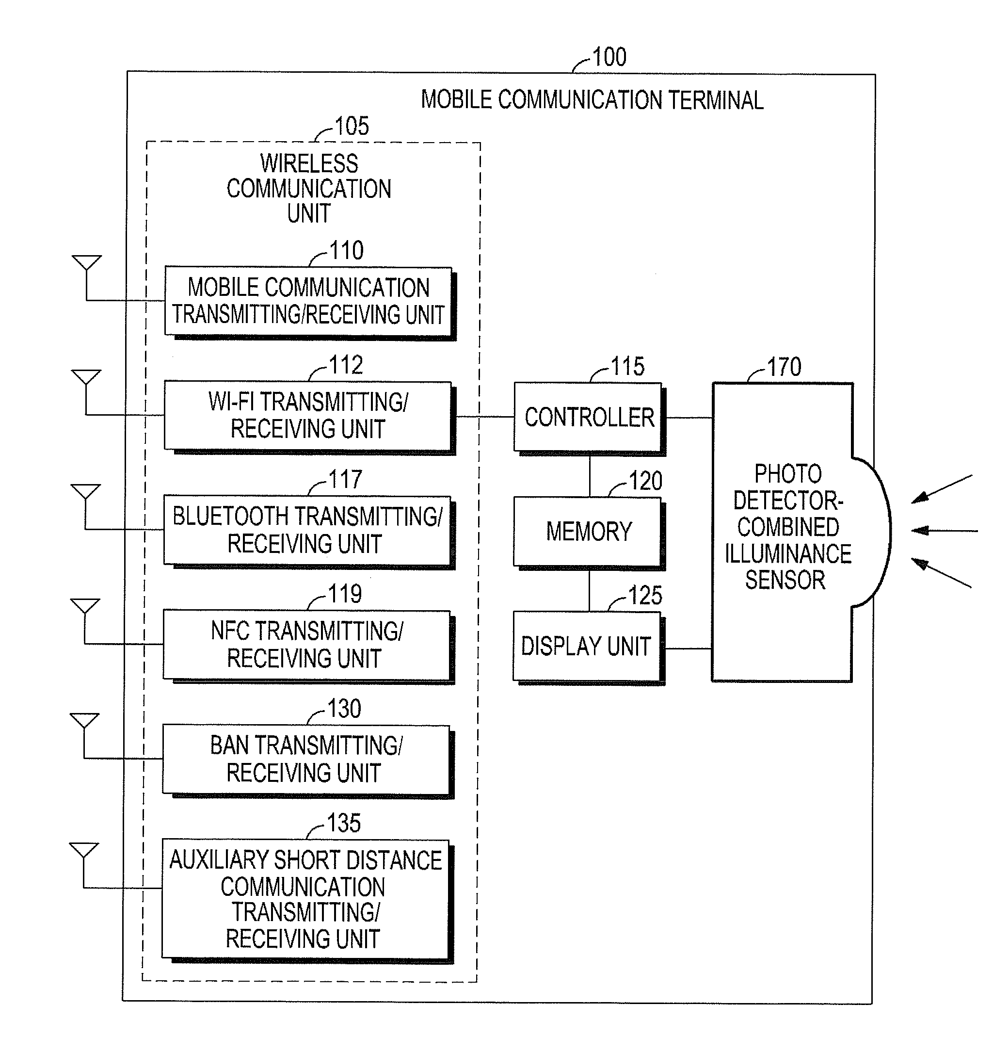
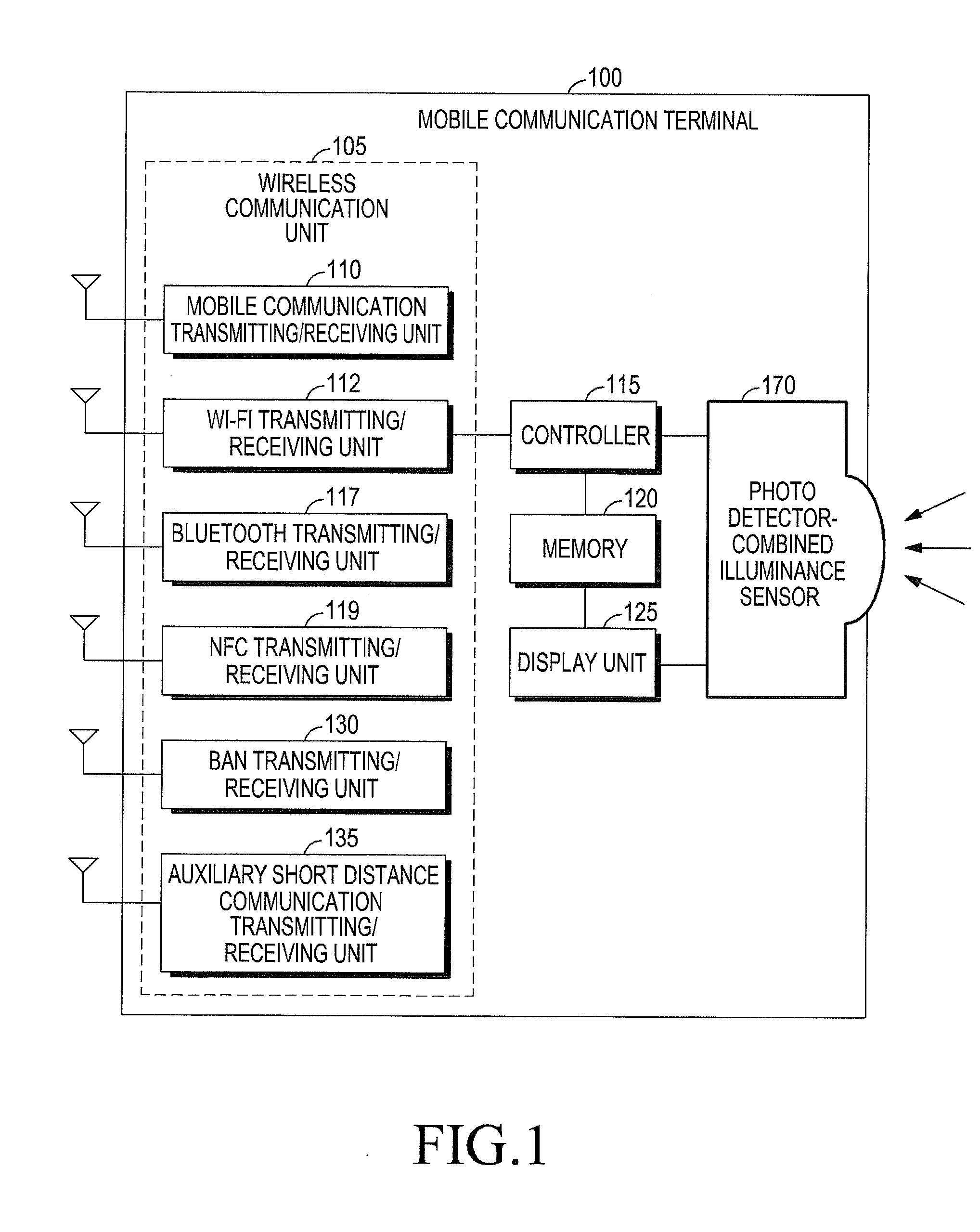
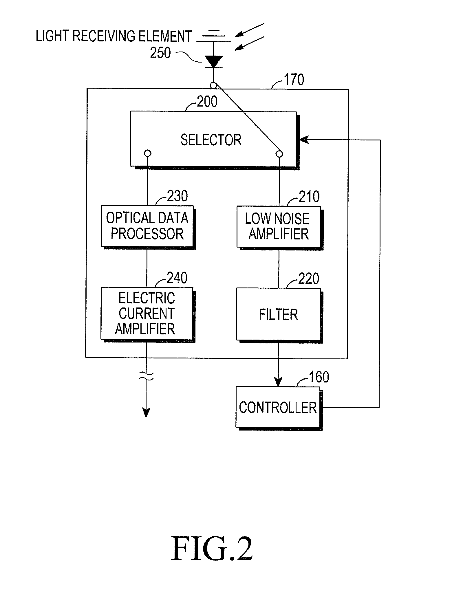
[0017]FIGS. 1 through 4, discussed below, and the various embodiments used to describe the principles of the present disclosure in this patent document are by way of illustration only and should not be construed in any way to limit the scope of the disclosure. Those skilled in the art will understand that the principles of the present disclosure may be implemented in any suitably arranged Visible Light Communication (VLC) devices. Hereinafter, an exemplary embodiment of the present invention will be described in detail with reference to the accompanying drawings. In the following description, the same elements will be designated by the same reference numerals although they are shown in different drawings. Further, in the following description, a detailed explanation of known related functions and constitutions may be omitted to avoid unnecessarily obscuring the subject matter of the present invention.

[0018]The following description presents a representative embodiment of the present...


PUM


Abstract

According to one embodiment, a photo detector-combined illuminance sensor includes a circuit for a Photo Detector (PD) function to detect the illuminance of the ambient environment. The illuminance sensor operates under the control of a controller in a visible light communication terminal. When an optical signal detected by the illuminance sensor is a visible light communication signal, the controller switches to cause the illuminance sensor to operate as the photo detector for the visible light communication in a visible light communication mode.

Description

CROSS-REFERENCE TO RELATED APPLICATION(S) AND CLAIM OF PRIORITY[0001]The present application is related to and claims the priority under 35 U.S.C. §119(a) of an application entitled “Method Of Visible Light Communication Using Illuminance Sensor And Mobile Communication Terminal For The Same” filed in the Korean Industrial Property Office on Jul. 12, 2011 and assigned Serial No. 10-2011-0069159, the contents of which are hereby incorporated by reference.TECHNICAL FIELD OF THE INVENTION[0002]The present invention relates generally to communication devices, and more particularly, to a method for performing visible light communication using an illuminance sensor and the illuminance sensor for the method.BACKGROUND OF THE INVENTION[0003]Visible Light Communication (VLC) generally uses a Light Emitting Diode (LED) and a Photo Diode (PD) for transmission and reception of data using visible light. Therefore, VLC systems include a light source, which is provided by an LED or a Laser Diode (...

Claims


Application Information

Patent Timeline
Patent Type & Authority Applications(United States)
IPC IPC(8): H04B10/22
CPCH04W88/06H04B10/116H04W88/02H04B10/40
Inventor SON, JAE-SEUNGBAE, TAE-HANWON, EUN-TAE
Owner SAMSUNG ELECTRONICS CO LTD
Why Eureka
Try Eureka