
Injection device with cammed ram assembly

a technology of injection device and cammed ram, which is applied in the direction of intravenous device, infusion needle, other medical devices, etc., can solve the problems of accidental firing, dangerously high pressure, and medicament to be expelled from the devi

Active Publication Date: 2013-01-17
ANTARES PHARMA
View PDF1 Cites 142 Cited by
  • Summary
  • Abstract
  • Description
  • Claims
  • Application Information

AI Technical Summary

Benefits of technology

The present disclosure provides an injector device that includes a trigger mechanism, an energy source, and a user-operable firing-initiation member. The trigger member has a retainer portion and a ram assembly with a ram that can pressurize a medicament container for expelling the medicament. The energy source is associated with the ram to power it, and the user-operable firing-initiation member is operable for causing an axial rotation between the trigger engagement member and the retainer portion from a pre-firing condition to a firing condition in which the trigger engagement member is released from the retainer portion to allow the energy source to fire the ram. The injector can also include a skin-contacting member that can retract a needle guard and expose the needle for injection. The injector can also include a container support that locks the injector after an injection. The technical effects of the present disclosure include improved safety and reliability, as well as a simplified and user-friendly design.

Problems solved by technology

Because of the stored energy associated with the trigger and injection mechanisms, accidental firing can occur due to sudden movements during shipping or due to mishandling of the device by a user including accidental actuation of the trigger mechanism.
Accidental firing of the injection mechanism can cause the medicament to be expelled from the device, which can be at a dangerously high pressure, depending on the type of injection device.
Further, accidental firing can cause an injection needle to move forward with respect to the device with sufficient force to penetrate the skin.
Additionally, the dimensions of many components incorporated in injectors typically constrain the design of many injectors.
Further, proximal movement of the user-operable firing-initiation member can be blocked by the ram assembly when the injector is locked-out.

Method used


Image

  • Injection device with cammed ram assembly
  • Injection device with cammed ram assembly
  • Injection device with cammed ram assembly

Examples


Embodiment Construction

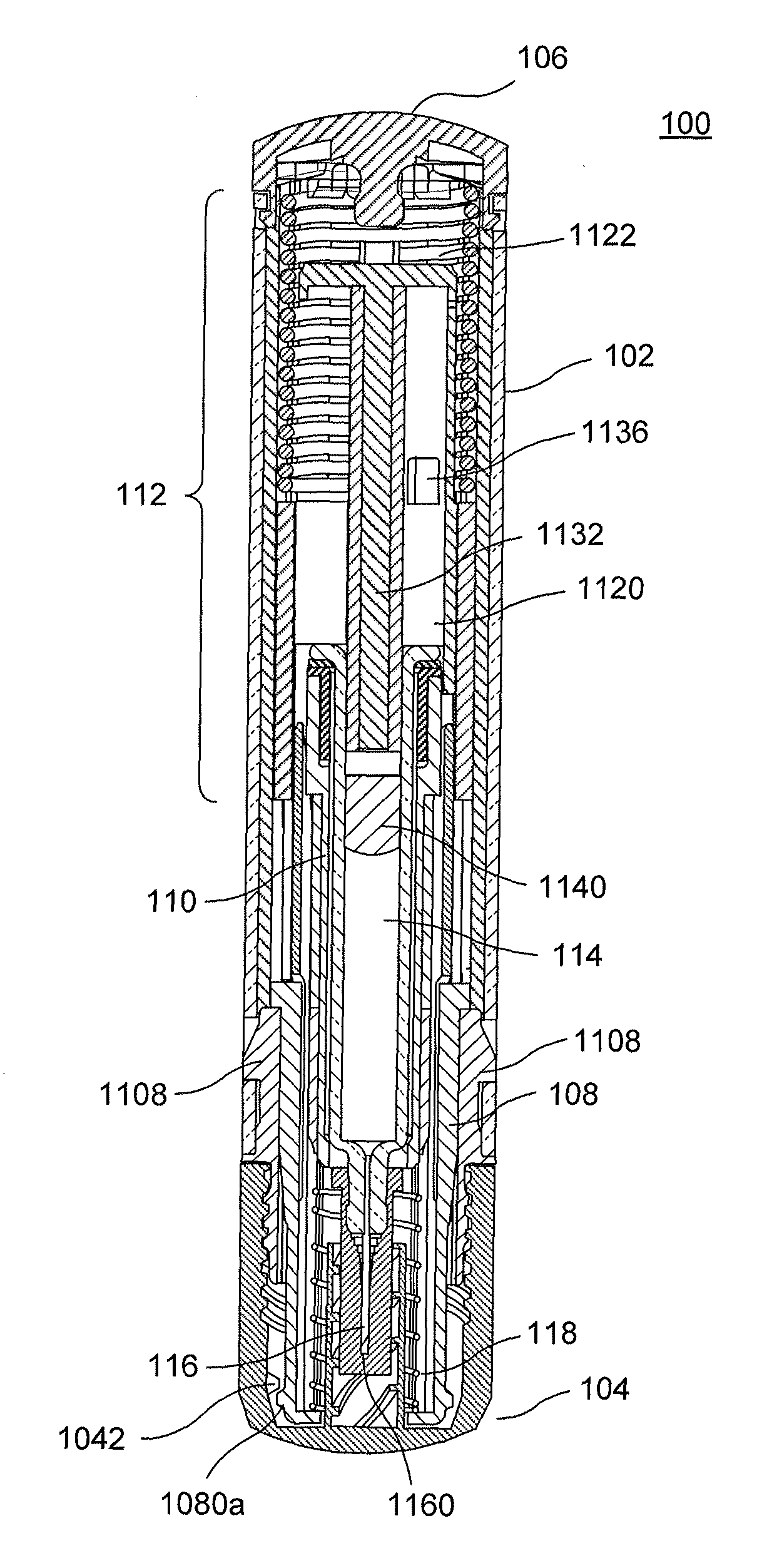
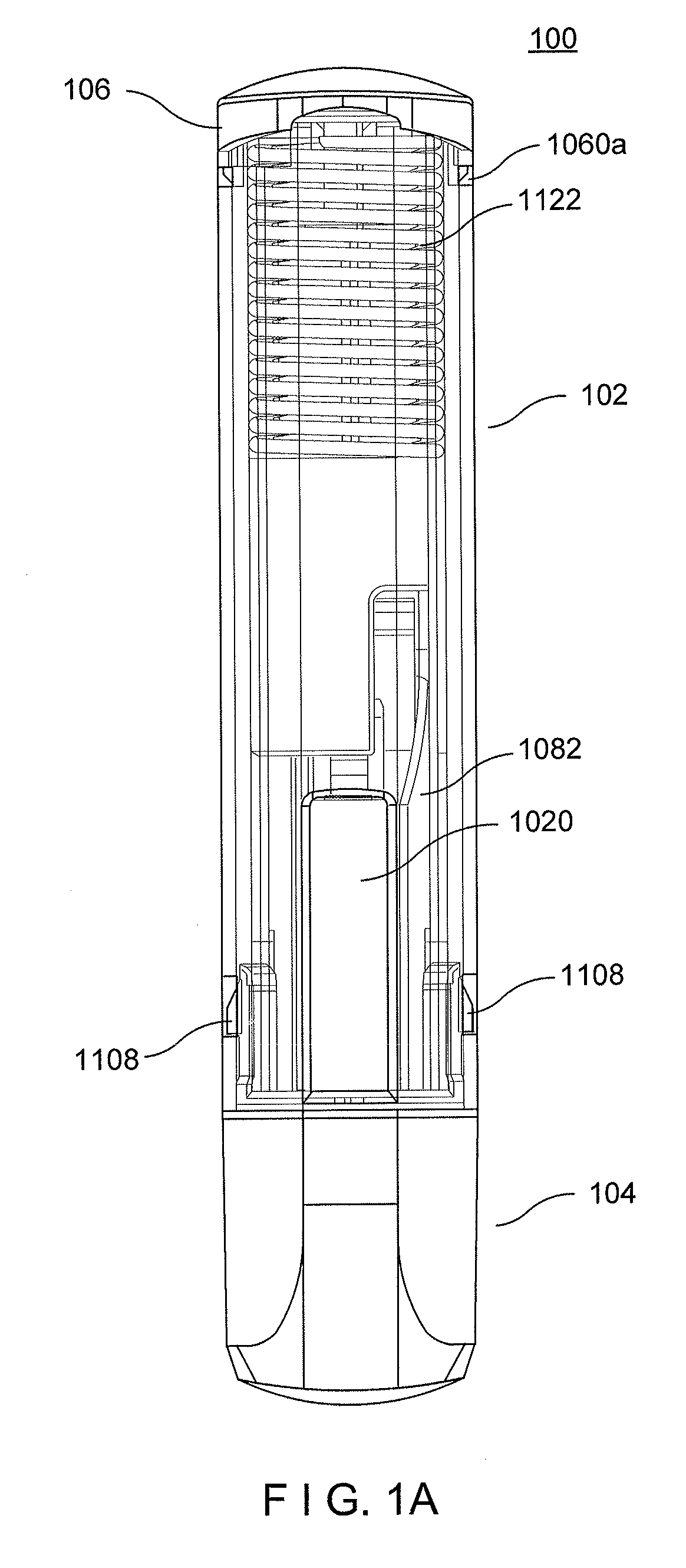
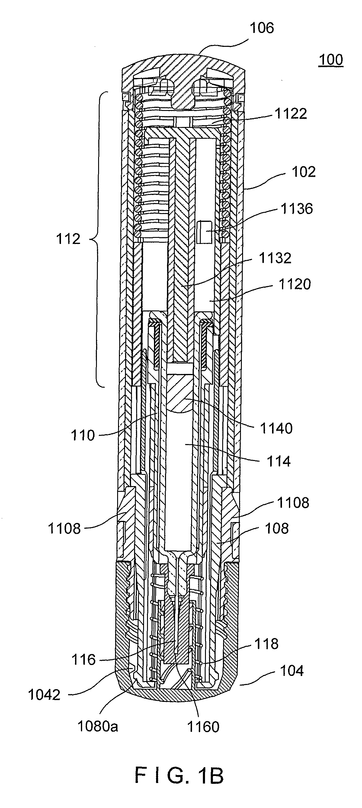
[0034]FIG. 1A shows an exemplary injection device 100 according to an exemplary embodiment of the present disclosure. It is noted that, in the context of this disclosure, the terms “distal” and “proximal” are used in reference to the position of the injection device relative to a user of the injection device when merely held by a user. Accordingly, a point located distal to a second point would be further from the user (i.e., towards an injection end of the injection device) and vice versa. As shown in the drawings, the exemplary injection device 100 is preferably a needle assisted jet injection device, although a person having ordinary skill in the art will understand alternative embodiments employing certain features herein can be configured as needle-free jet injectors, or as low-pressure auto-injectors or other mechanized injectors. According to certain exemplary embodiments, injection device 100 can be a one-time disposable needle-assisted jet injector with a lock-out feature. ...


PUM


Abstract

An exemplary embodiment of the present disclosure can provide an injector including a trigger mechanism, an energy source, and a user-operable firing-initiation member. The trigger member can include a trigger member having a retainer portion, and a ram assembly having a ram configured to pressurize a medicament container for expelling a medicament therefrom and a trigger engagement member configured to engage the retainer portion of the trigger member in a pre-firing condition. The energy source can be associated with the ram for powering the ram to expel the medicament, and the user-operable firing-initiation member can be operable for causing an axial rotation between the trigger engagement member and the retainer portion from the pre-firing condition to a firing condition in which the trigger engagement member is released from the retainer portion to allow the energy source to fire the ram.

Description

FIELD OF THE DISCLOSURE[0001]The present disclosure relates to injection devices, and in particular to a needle assisted jet injector.BACKGROUND INFORMATION[0002]Various injection devices exist that employ an automated mechanism to actuate injection of a liquid medicament into a patient. Examples of such devices include jet injectors (both needle-free and needle-assisted) and traditional, low-pressure auto-injectors (that provide, for example, mechanized delivery of a traditional, finger-powered hypodermic syringe injection). Although the precise mechanisms used to complete an injection can vary, most include a feature that stores kinetic energy that can be used to drive an injection mechanism during use. Further, many injectors include a trigger mechanism configured to ensure that the kinetic energy remains stored until an injection is desired, whereby actuation of the trigger releases the injection mechanism, allowing the stored kinetic energy to drive the injection mechanism to c...

Claims


Application Information

Patent Timeline
IPC IPC(8): A61M5/20
CPCA61M5/2033A61M5/30A61M5/3007A61M5/3204A61M2005/3247A61M2005/2013A61M2005/206A61M2005/2073A61M5/326A61M5/5086A61M2205/584
Inventor KRAMER, THOMASRUST, MATTHEW HOWARDGOUDREAU, PAUL MICHAELHOEFT, PETER ANTHONYSUND, JULIUS CRAIGSADOWSKI, PETER L.
Owner ANTARES PHARMA
Learn More