Spinal rod system and method

a technology of spinal rods and actuator arms, which is applied in the field of spinal rod systems and methods, can solve the problems of not being able to relieve the symptoms associated with these disorders, and achieve the effect of facilitating the axial movement of the actuator arm and the axial movement of the reducer

Active Publication Date: 2013-01-17
WARSAW ORTHOPEDIC INC
View PDF6 Cites 74 Cited by
  • Summary
  • Abstract
  • Description
  • Claims
  • Application Information

AI Technical Summary

Benefits of technology

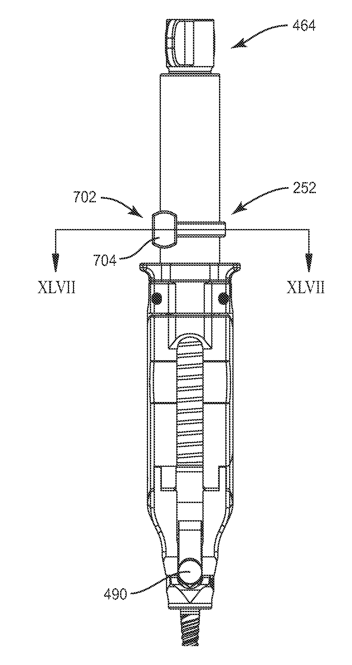
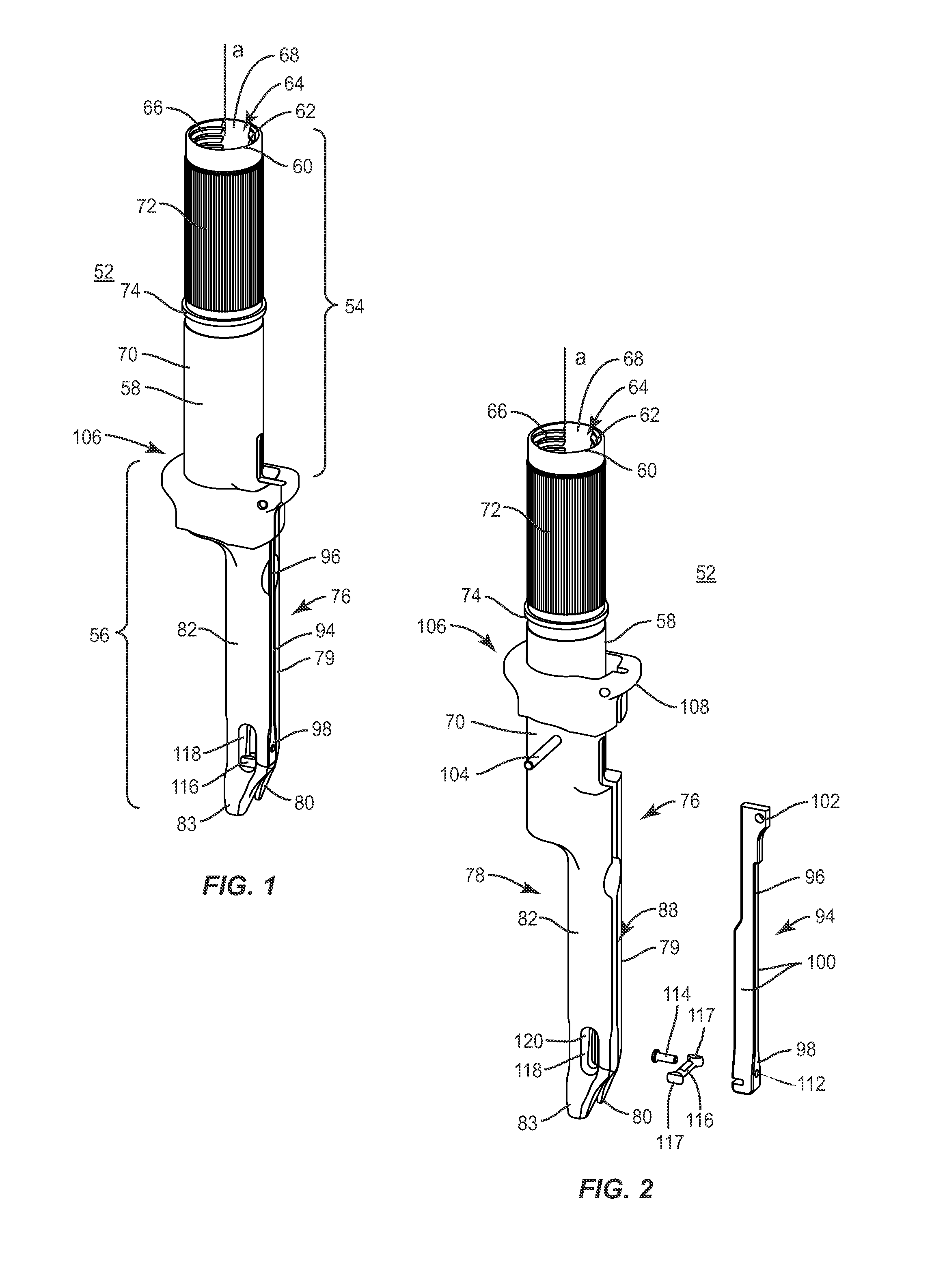
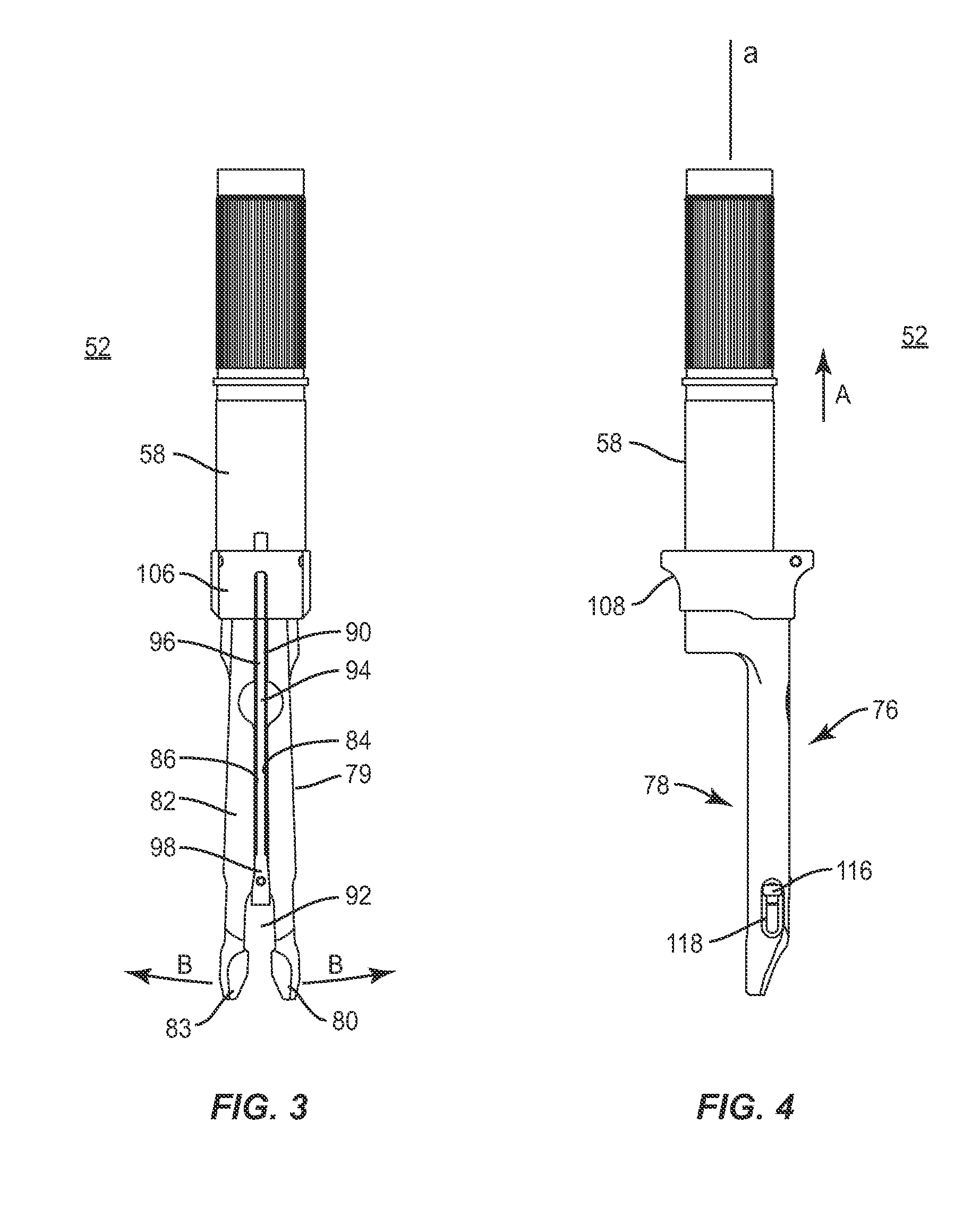
[0007]In one embodiment, the spinal rod system includes at least one bone fastener. An extender is disposed along a longitudinal axis thereof and includes a cylindrical proximal portion that defines an inner cavity having an inner surface and a distal portion that includes an arm extending along the longitudinal axis and defining at least a portion of a vertebral construct cavity disposed in communication with the inner cavity. The arm extends distally from the proximal portion and includes a first movable leg extension defining a distal engagement part and a second movable leg extension defining a distal engagement part. The leg extensions extend in a cantilevered configuration from the proximal portion and are oriented to define an axial arm cavity therebetween. The extender further includes an actuator arm axially movable within the axial arm cavity and a handle, connected with the actuator arm, which includes a grip surface configured to facilitate axial movement of the actuator arm. The actuator arm is engageable with the leg extensions to cause the distal engagement parts to move in a direction transverse to the longitudinal axis between an open position and a closed position such that the distal engagement parts releasably capture a bone fastener. An inserter extends between a proximal end and a distal end thereof. The inserter is slidably disposable in the inner cavity and along the inner surface such that the distal end of the inserter engages the at least one bone fastener in a configuration to support the at least one bone fastener with the distal engagement parts. A reducer extends between a proximal end and a distal end thereof. The reducer is disposable in the inner cavity and defines an outer threaded surface. The outer threaded surface engages the inner surface of the proximal portion of the extender to facilitate axial movement of the reducer relative to the extender such that the distal end of the reducer includes a pusher that is engageable with a vertebral construct disposed in the vertebral construct cavity in a configuration to move the vertebral construct into engagement with a bone fastener. The pusher is rotatable relative to the reducer and configured to engage the first arm to prevent rotation of the pusher relative to the at least one first arm.

Problems solved by technology

Non-surgical treatments, such as medication, rehabilitation and exercise can be effective, however, may fail to relieve the symptoms associated with these disorders.

Method used


Image

  • Spinal rod system and method
  • Spinal rod system and method
  • Spinal rod system and method

Examples


Embodiment Construction

[0057]The exemplary embodiments of the surgical system and related methods of use disclosed are discussed in terms of medical devices for the treatment of musculoskeletal disorders and more particularly, in terms of a surgical system for implant delivery to a surgical site and a method for treating a spine. It is envisioned that the surgical system can include an instrument system having extenders, reducers and translators, which can be used to introduce a vertebral construct such as a rod to a bone fastener such as a bone anchor or bone screw. For example, an extender can include bone anchor attachment features on one or both sides of the instrument. It is contemplated that the system may be used with a reducer assembly to introduce a rod into a bone fastener.

[0058]It is envisioned that the system may include instruments that are connected or attach to an extender(s) such as, for example, a lateral translation handle or derotaton instruments. It is further envisioned that the syste...


PUM


Abstract

A spinal rod system includes a first instrument extending between a proximal portion and a distal portion along a longitudinal axis thereof. The proximal portion defines an inner cavity extending along the longitudinal axis. The first instrument includes a first arm extending along the longitudinal axis. The first arm defines a portion of a vertebral construct cavity disposed in communication with the inner cavity and includes a distal end being configured to engage a bone fastener. Methods of use are disclosed.

Description

TECHNICAL FIELD[0001]The present disclosure generally relates to medical devices for the treatment of musculoskeletal disorders, and more particularly to a surgical system for implant delivery to a surgical site and a method for treating a spine.BACKGROUND[0002]Spinal pathologies and disorders such as scoliosis and other curvature abnormalities, kyphosis, degenerative disc disease, disc herniation, osteoporosis, spondylolisthesis, stenosis, tumor, and fracture may result from factors including trauma, disease and degenerative conditions caused by injury and aging. Spinal disorders typically result in symptoms including deformity, pain, nerve damage, and partial or complete loss of mobility.[0003]Non-surgical treatments, such as medication, rehabilitation and exercise can be effective, however, may fail to relieve the symptoms associated with these disorders. Surgical treatment of these spinal disorders includes correction, fusion, fixation, discectomy, laminectomy and implantable pr...

Claims


Application Information

Patent Timeline
Patent Type & Authority Applications(United States)
IPC IPC(8): A61B17/70A61B17/56
CPCA61B17/7076A61B17/7086A61B17/7085A61B17/7032
Inventor REZACH, WILLIAM ALANMAY, JASON
Owner WARSAW ORTHOPEDIC INC
Why Eureka
Try Eureka