
Thruster devices and methods of making thruster devices for use with thrust vector control systems

Inactive Publication Date: 2013-01-24
AUTOLIV ASP INC
View PDF6 Cites 5 Cited by
  • Summary
  • Abstract
  • Description
  • Claims
  • Application Information

AI Technical Summary

Benefits of technology

[0007]In accordance with one or more aspects of the present disclosure, thruster devices and/or lateral thrust modules are provided for use in a flight body, such as a rocket or missile, which thruster devices are adapted to facilitate use of propellant materials having relatively low burning rates, while still achieving relatively short a

Problems solved by technology

The conventional single grain of solid propellant is typically formed large enough to at least substantially fill a chamber in the lateral thrust motor, resulting in a substantially thick grain.
However, when creating the chemistry for such high burn-rate propellant material, it is more difficult to keep the burn rate consistent from part to part.
For example, fast-burning solid propellant materials typically employ very fine powders that are costly to produce, and that can vary sub

Method used


Image

  • Thruster devices and methods of making thruster devices for use with thrust vector control systems
  • Thruster devices and methods of making thruster devices for use with thrust vector control systems
  • Thruster devices and methods of making thruster devices for use with thrust vector control systems

Examples


Example

[0020]The illustrations presented herein are, in some instances, not actual views of any particular thruster devices, lateral thrust modules or flight bodies, but are merely idealized representations which are employed to describe the present disclosure. Additionally, elements common between figures may retain the same numerical reference designation.

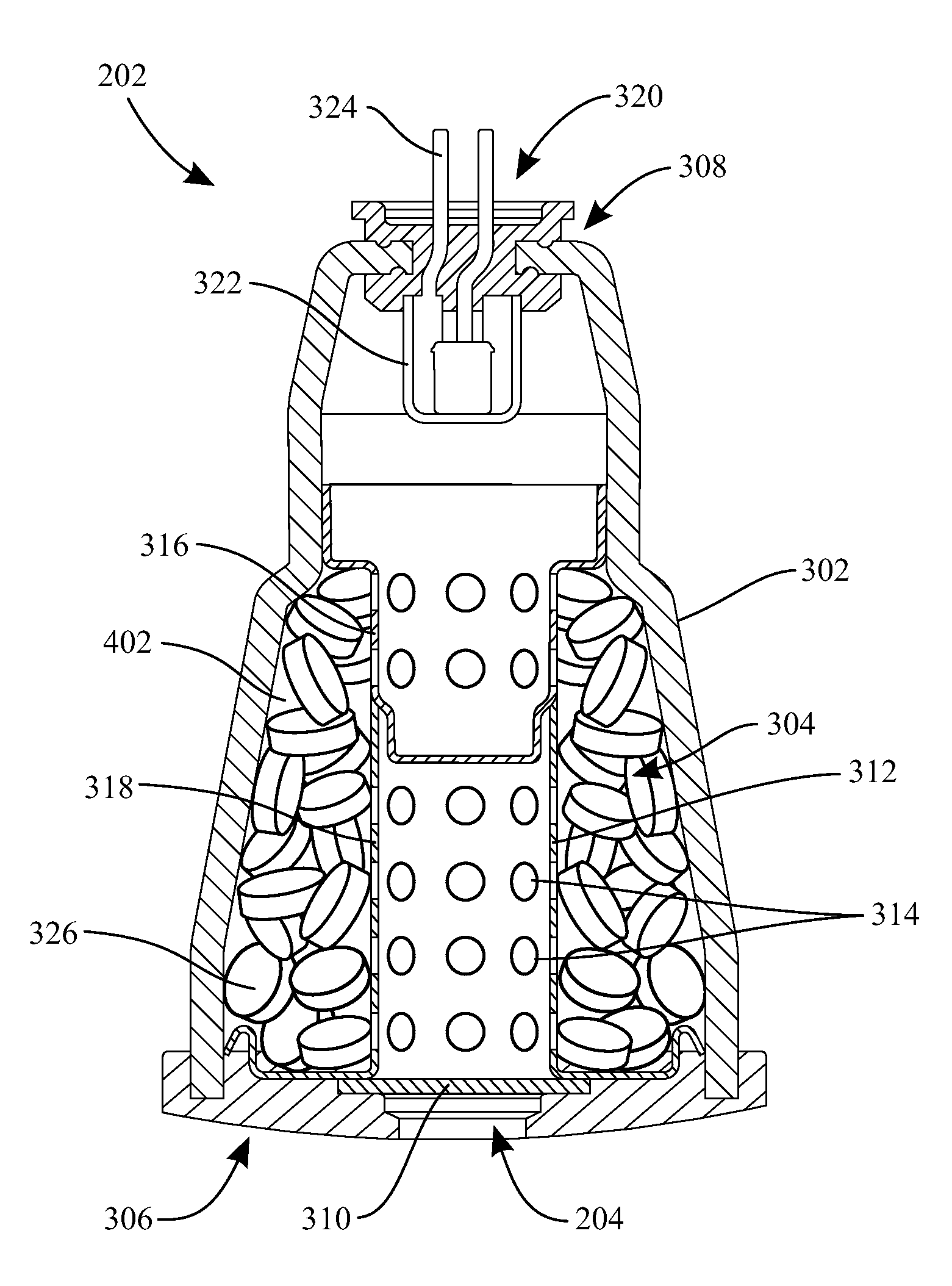
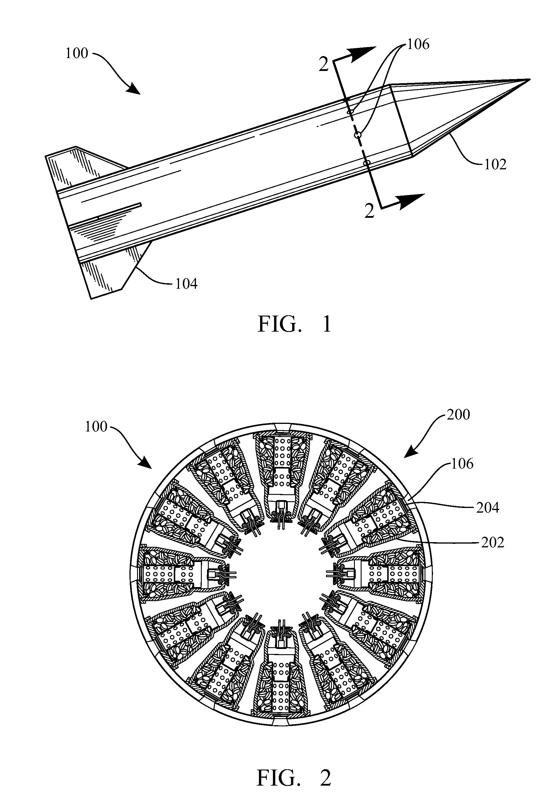
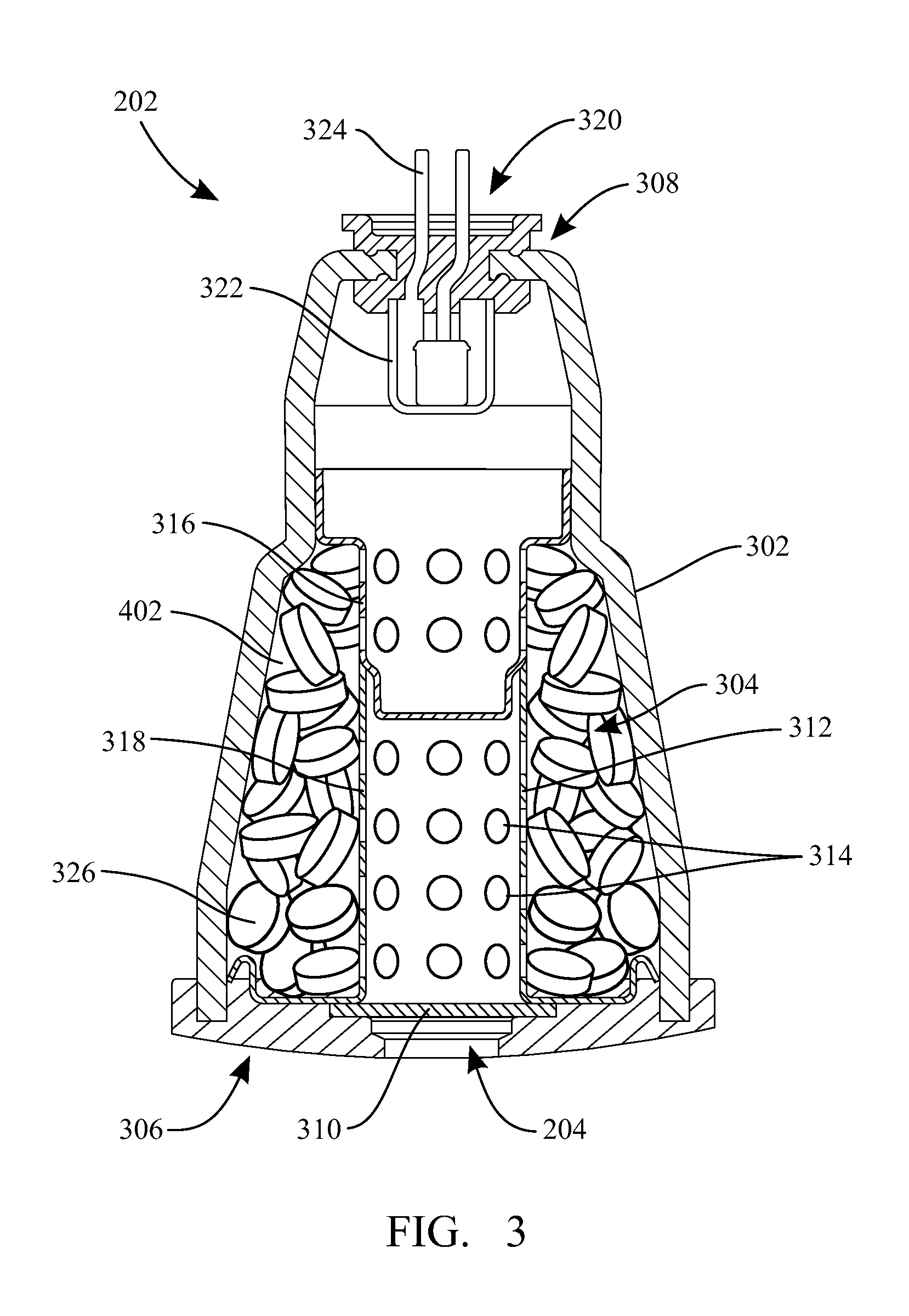
[0021]Various embodiments of the present disclosure include thruster devices and thrust modules for use in various flight bodies. FIG. 1 is a side elevation view showing an example of a flight body 100, embodied as a rocket or missile. Such a flight body 100 may typically include a generally cylindrical shape, with a projectile tip (or nose cone) 102 at a leading end, and a plurality of stabilizing fins 104 at a trailing end. Located generally between the leading and trailing ends, the flight body 100 may include a plurality of apertures 106 around a circumference thereof. Each of the plurality of apertures 106 is associated with a thru...


PUM

PropertyMeasurementUnit
Shapeaaaaaaaaaa

Abstract

Thruster devices for use with a lateral thrust module and/or a flight body are adapted to achieve short action times with relatively slow burning propellant materials. Such thruster devices include a combustion chamber with a plurality of propellant grains disposed therein. At least some of the plurality of propellant grains are formed into a selected shape. Methods of making thruster devices include forming a housing comprising a first longitudinal end and an opposing second longitudinal end. The housing is formed to define a combustion chamber. A plurality of propellant grains are disposed in the combustion chamber of the housing, where each propellant grain comprises a selected shape. An igniter is coupled to the housing, which igniter is adapted to initiate a combustion of the plurality of propellant grains during deployment of the thruster device.

Description

TECHNICAL FIELD[0001]The present disclosure relates generally to thruster devices for controlling the attitude of a flying body. More specifically, various embodiments of the present disclosure relate to vector thrust devices and methods of making vector thrust devices for use in thrust vector control systems of flying bodies.BACKGROUND[0002]Various self-propelled flying bodies, such as rockets and missiles, are typically employed for a variety of uses, such as military and scientific. One of the basic goals of the technology of flight bodies is to improve the maneuverability of the body. The maneuverability of a flight body is related to its ability to change its flight path. Since lateral forces may cause a flight body to change its flight path, the maneuverability of a flight body is related to its ability to develop lateral forces. Various approaches are conventionally applied to develop lateral forces for controlling the attitude and direction of the flight body (e.g., controll...

Claims


Application Information

Patent Timeline
IPC IPC(8): F02K9/32F02K9/95
CPCF02K9/10F02K9/34Y10T29/49346F02K9/95F02K9/80
Inventor HOFFMAN, ISAACHUSSEY, BRETTCLARK, RANDYCLARK, KENNETH J.
Owner AUTOLIV ASP INC
Learn More