Heat dissipation device

Inactive Publication Date: 2013-01-24
FU ZHUN PRECISION IND SHENZHEN +1
View PDF0 Cites 1 Cited by
  • Summary
  • Abstract
  • Description
  • Claims
  • Application Information

AI Technical Summary

Problems solved by technology

This type of heat dissipation device is bulky an

Method used


Image

  • Heat dissipation device
  • Heat dissipation device
  • Heat dissipation device

Examples


Embodiment Construction

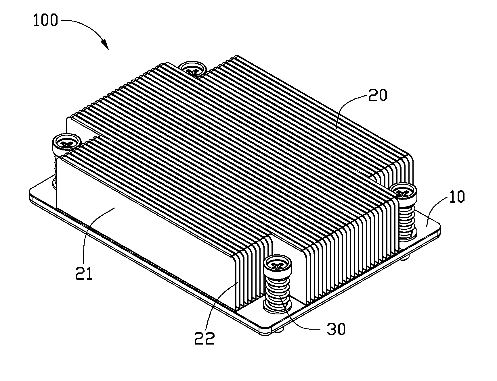
[0009]Referring to FIG. 1, a heat dissipation device 100 is shown. The heat dissipation device 100 includes a base 10 and a fin group 20 mounted on the base 10. The heat dissipation device 100 is used to dissipate heat generated from a heat-generating component (not shown).

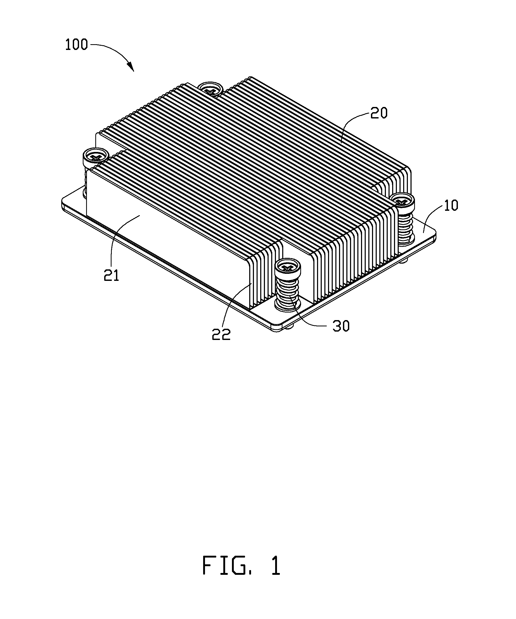
[0010]Referring also to FIGS. 2-3, the base 10 is rectangular and thin, and includes a container 16, a heat pipe 14, and two supporting members 13. The container 16 receives the supporting members 13 and the heat pipe 14 therein.

[0011]The container 16 is made of heat conductive material and includes a rectangular baffle plate 11 and a cover 12 engaging with the baffle plate 11 to define a receiving chamber 15 therebetween. Four through holes 111 are respectively defined in corners of the baffle plate 11. The cover 12 includes a rectangular supporting plate 121 and four sidewalls 122 extending from edges of the supporting plate 121 to the baffle plate 11. The baffle plate 11 connects top ends of the sidewalls 122. ...


PUM


Abstract

A heat dissipation device includes a base and a fin group fixed on the base. The base includes a container, a flattened heat pipe and a solid supporting member. The container includes a baffle plate and a cover engaging with the baffle plate to define a receiving chamber therebetween. The heat pipe and the supporting member are housed in the receiving chamber. Opposite sides of the heat pipe and the supporting member respectively abut against the baffle plate and the cover of the container.

Description

BACKGROUND[0001]1. Technical Field[0002]The present disclosure relates to heat dissipation devices.[0003]2. Description of Related Art[0004]Heat dissipation devices are used to remove heat from heat-generating electronic components such as central processing units (CPUs) and others, keeping the electronic components within safe working temperature limits, thereby enabling stable operation of the electronic components. A typical heat dissipation device includes a base for contacting an electronic component and absorbing heat therefrom, a number of fins located at a top of the base, and a heat pipe connecting the base and the fins. The heat pipe has one end embedded in the base and the other end extending through the fins. This type of heat dissipation device is bulky and is not suitable for portable electronic device.[0005]What is called for, then, is a heat dissipation device which can overcome the limitations described.BRIEF DESCRIPTION OF THE DRAWINGS[0006]FIG. 1 is an assembled, ...

Claims


Application Information

Patent Timeline
IPC IPC(8): F28D15/04
CPCH01L23/3672H01L23/4006H01L23/427H01L23/467H01L2924/0002H01L2924/00F28D15/0275
Inventor PENG, XUE-WENLI, WEIQIN, JI-YUNLIU, HAO-XIA
Owner FU ZHUN PRECISION IND SHENZHEN
Why Eureka
Try Eureka