

Nail print apparatus
a printing apparatus and nail technology, applied in the field of nail printing apparatus, can solve the problems of cramped non-printing fingers, difficult to hold the printing finger in a predetermined position during printing processing, and create a feeling of pressure, so as to achieve the effect of not imposing excessive burden on non-printing fingers and easy holding
- Summary
- Abstract
- Description
- Claims
- Application Information
AI Technical Summary
Benefits of technology
Problems solved by technology
Method used
Image

Examples
first embodiment
[0027]The first embodiment of the nail print apparatus according to the present invention will be explained referring to FIGS. 1 to 6.
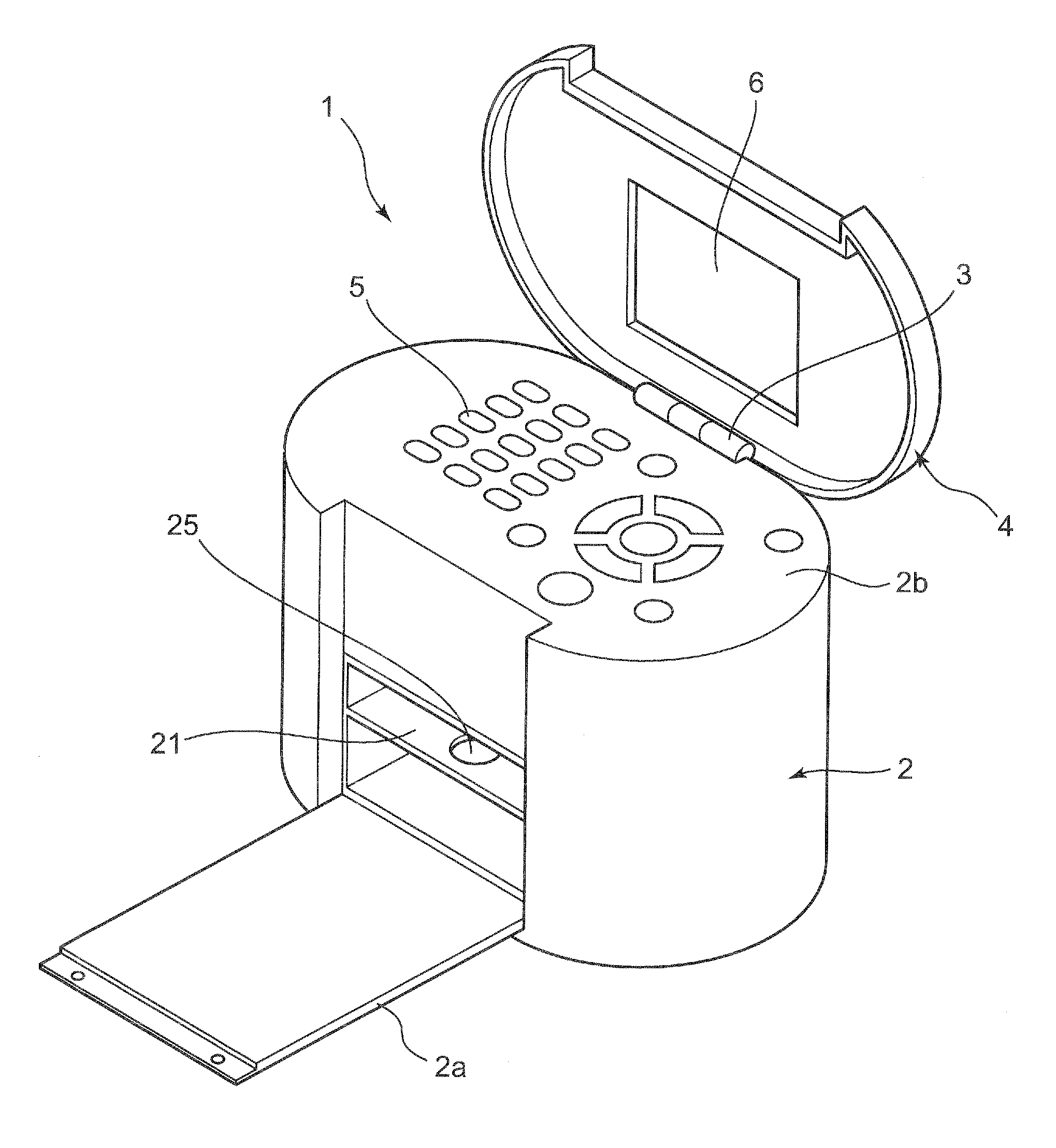
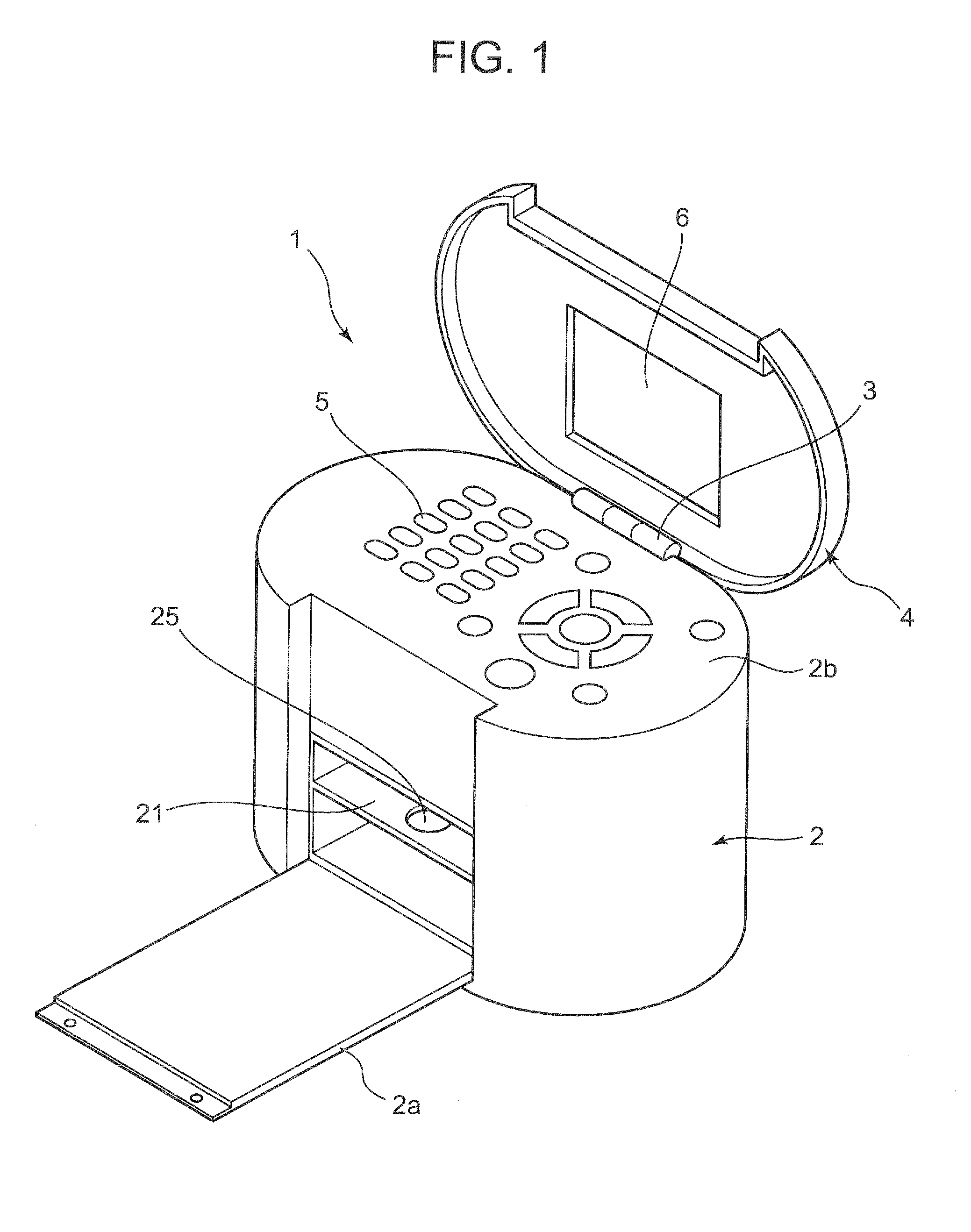
[0028]As shown in FIG. 1, a nail print apparatus 1 includes a case main body 2 and a cover 4.
[0029]A display unit 6 is provided on the inner surface of the cover 4. The display unit 6 is configured by including a liquid crystal panel (LCD: Liquid Crystal Display) and such like, for example. On the display unit 6, a photographed finger nail image of a printing finger, the nail in the finger nail image, the outline of the printing finger, a nail image pattern to be printed on the nail of the printing finger, thumbnail images for confirming the design and such like are arbitrarily displayed, for example.
[0030]The cover 4 is joined to the case main body 2 via a hinge 3 which is provided at the rear end portion of the upper surface of the case main body 2.
[0031]On the other hand, the case main body 2 is formed in an oval shape in a plan view. An opening / cl...
second embodiment
[0056]FIGS. 7A and 7B illustrate the placement unit of a nail print apparatus of the second embodiment.
[0057]As shown in FIG. 7A, a placement unit 51 of the nail print apparatus 1 includes a placement board 51a on which fingertips are placed, a placement bar 51b which is located in front of the placement board 51a and bases or roots of fingers are placed thereon, and a thumb hole unit 51c which is formed between the placement board 51a and the placement bar 51b. Here, the base of the finger includes the palm. The same shall apply hereinafter.
[0058]A printing finger positioning unit 52 which includes a printing finger inlet port 52a is provided on the placement board 51a, and non-printing finger receiving units 53a and 53b are formed respectively at the sides of the printing finger positioning unit 52. The printing finger positioning unit 52 and the non-printing finger receiving units 53a and 53b constitute a first finger receiving unit 50a.
[0059]The non-printing finger receiving un...
third embodiment
[0065]FIGS. 8A and 8B illustrate a placement unit of the nail print apparatus of the third embodiment.
[0066]As shown in FIG. 8A, a placement unit 61 of the nail print apparatus 1 includes a placement board 61a on which fingertips are placed, a placement bar 61b which is located in front of the placement board 61a and bases or roots of fingers are placed thereon, and a thumb hole unit 61c which is formed between the placement board 61a and the placement bar 61b.
[0067]A printing finger positioning unit 62 which includes a printing finger inlet port 62a is provided on the placement board 61a, and non-printing finger receiving units 63a and 63b are formed respectively at the sides of the printing finger positioning unit 62. The printing finger positioning unit 62 and the non-printing finger receiving units 63a and 63b constitute the first finger receiving unit 60a.
[0068]The non-printing finger receiving units 63a and 63b are used when any one of the index finger, middle finger, ring f...
PUM
 Abstract
Description
Claims
Application Information