Advanced infrared cut-off optical filters

a technology of optical filters and infrared cut-off, applied in the field of optical filter technology, can solve the problems of dramatic changes in refractive index and reflectivity of optical lenses, serious distortion of image color, and change in photographic image clarity, so as to reduce the angle dependence of optical filters

Active Publication Date: 2013-01-24
ZHEJIANG CRYSTAL OPTECH
View PDF16 Cites 9 Cited by
  • Summary
  • Abstract
  • Description
  • Claims
  • Application Information

AI Technical Summary

Benefits of technology

[0008]One aspect of the present disclosure includes an infrared cut-off optical filter. The infrared cut-off optical filter includes a substrate and a film structure. The substrate has a thickness and allows incoming lights to enter the optical filter at an incidence angle. The film structure is formed on the substrate to reduce an angle dependence of the optical filter with respect to the incoming lights. Further, the film structure contains a plurality of first type thin films with a first refractive index and a plurality of second type thin films with a second refractive index; the first type thin films and the second type thin films are arranged alternately; and thickness of individual films of the first type thin films and the second type thin films are controlled individually such that a substantial number of the first type thin films and the second type thin films have different thickness.

Problems solved by technology

However, wave optics theory has proved: the oblique incident light can produce polarization and lead to change in the refractive index and reflectivity of the optical lens.
But if the incident light angle changes beyond 5°, the change in the refractive index and reflectivity may be dramatic.
If the field of view of the camera is 60°, then the change in the refractive index or reflectivity may be more than 35%, or even reaches 50%˜85%, which can cause change in the photographic image clarity and serious distortion on the color of the image.
However, the blue glass is often costly and has few standard substrate thickness; the blue glass substrate is often in short supply; and the resin coating process is generally more complex, etc.
The low image clarity and uneven color can still exist, and only low-resolution optical imaging systems still use this type of IR film.

Method used


Image

  • Advanced infrared cut-off optical filters
  • Advanced infrared cut-off optical filters
  • Advanced infrared cut-off optical filters

Examples


Embodiment Construction

[0015]Reference will now be made in detail to exemplary embodiments of the invention, which are illustrated in the accompanying drawings. Wherever possible, the same reference numbers will be used throughout the drawings to refer to the same or like parts.

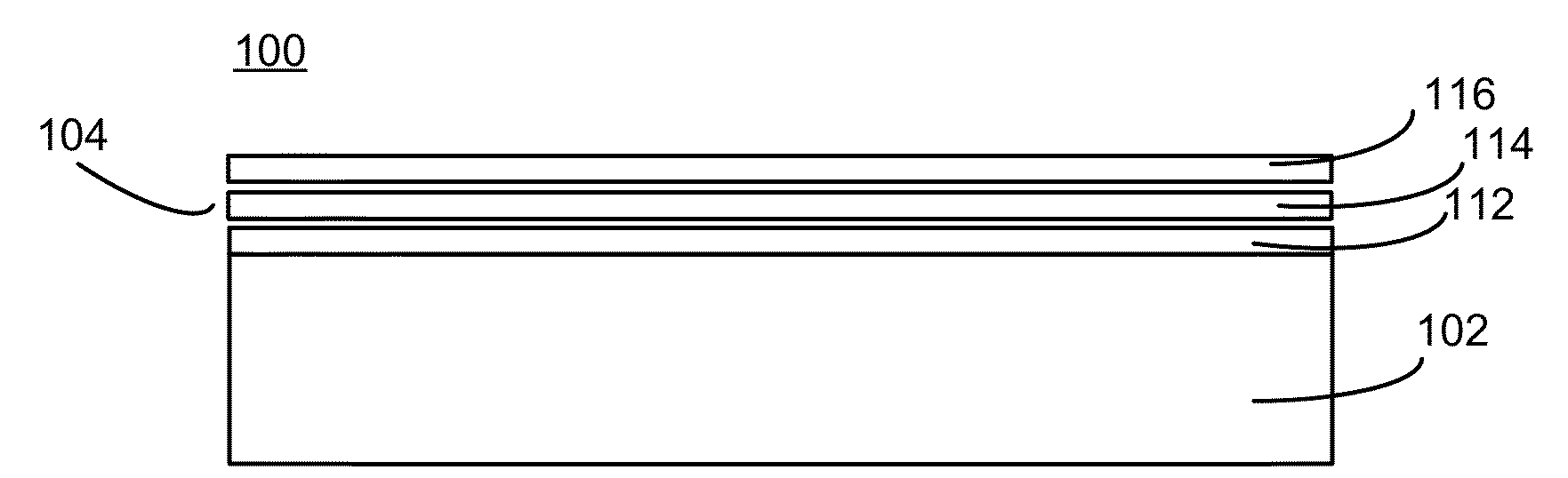
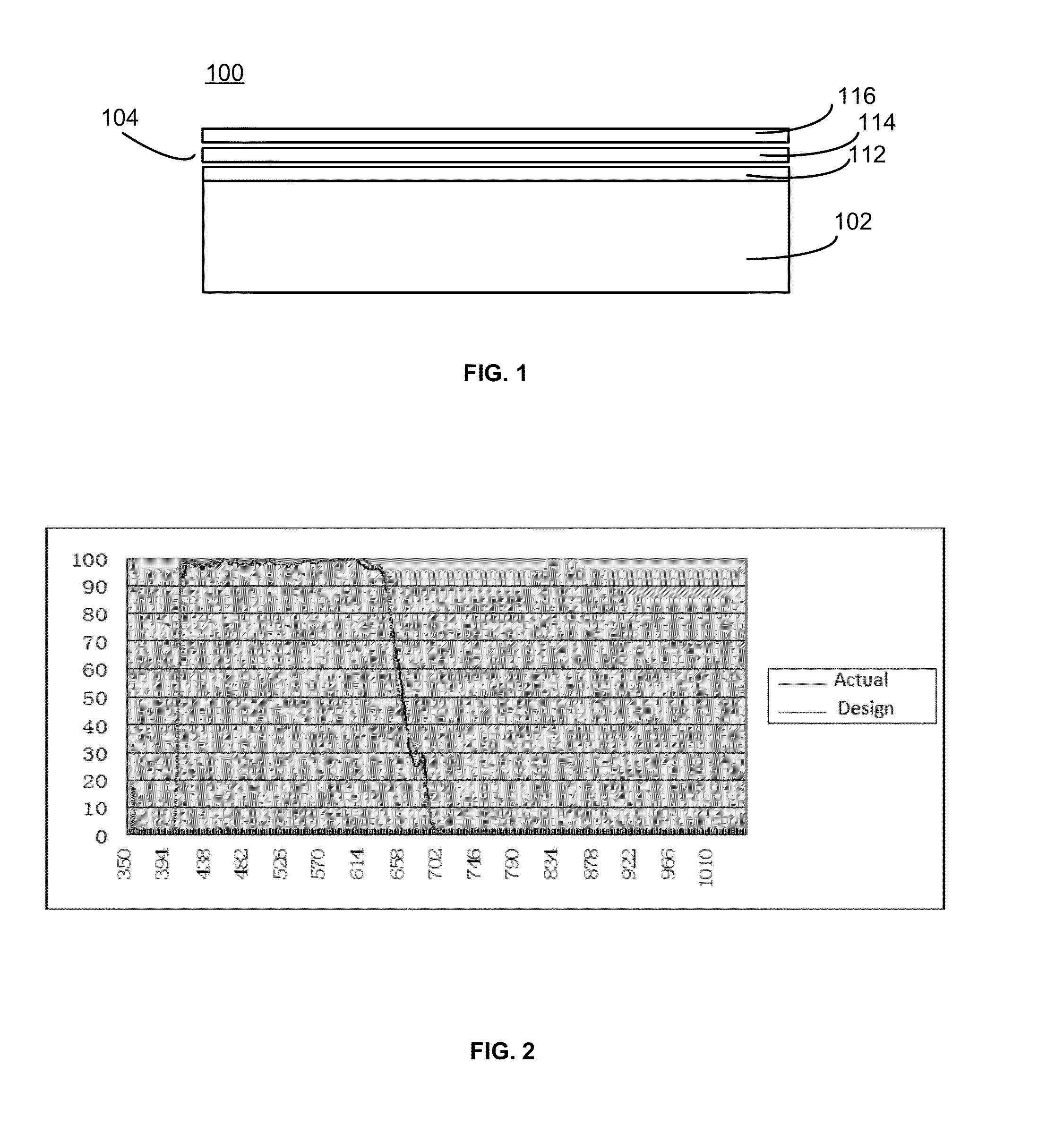
[0016]FIG. 1 illustrates an exemplary infrared cut-off optical filter 100 consistent with the disclosed embodiments. As shown in FIG. 1, optical filter 100 includes a substrate 102 and a filter film structure 104. Substrate 102 may include any appropriate material that can allow lights to pass through substrate 102. That is, filter substrate 102 has no special requirements on particular material, as long as visible light can pass through to the filter substrate 102. For example, filter substrate 102 may be an optical white flat glass or Schott D263Teco material.

[0017]The filter substrate 102 may have no special requirements on a particular thickness. Rather, the thickness of the filter substrate 102 may be in a certain range such t...


PUM

PropertyMeasurementUnit
incidence angleaaaaaaaaaa
angleaaaaaaaaaa
reflectivityaaaaaaaaaa

Abstract

An infrared cut-off optical filter includes a substrate and a film structure. The substrate has a thickness and allows incoming lights to enter the optical filter at an incidence angle. The film structure is formed on the substrate to reduce an angle dependence of the optical filter with respect to the incoming lights. Further, the film structure contains a plurality of first type thin films with a first refractive index and a plurality of second type thin films with a second refractive index; the first type thin films and the second type thin films are arranged alternately; and thickness of individual films of the first type thin films and the second type thin films are controlled individually such that a substantial number of the first type thin films and the second type thin films have different thickness.

Description

CROSS-REFERENCES TO RELATED APPLICATIONS[0001]This application claims the priority of Chinese patent application no. 201120260797.0, filed on Jul. 22, 2011, the entire contents of all of which are incorporated herein by reference.FIELD OF THE INVENTION[0002]The present invention relates to the field of optical filter technology and, more particularly, relates to techniques for designing and fabricating high-performance infrared cut-off optical filters.BACKGROUND[0003]Photographic technology has been in rapid development in recent decades. The progresses are mainly reflected in: (1) digital technology is used in cameras, and (2) the requirement of large field of view on cameras brings wide-angle and ultra wide-angle lens into reality. However, to successfully apply digital technology in cameras, the Moire fringes caused by using CCD or CMOS image sensors and the thermal fluctuation caused by infrared light need to be suppressed. Thus, an infrared cut-off filter needs to be installed ...

Claims


Application Information

Patent Timeline
Patent Type & Authority Applications(United States)
IPC IPC(8): G02B5/20H04N5/225G03B11/04
CPCG02B5/282C03C17/3417G02B5/285
Inventor WANG, JINWEI
Owner ZHEJIANG CRYSTAL OPTECH
Why Eureka
Try Eureka