Liquid crystal display device, active matrix substrate, liquid crystal panel, liquid crystal display unit, and television receiver

a liquid crystal display and active matrix technology, applied in static indicating devices, non-linear optics, instruments, etc., to achieve the effect of reducing the dependence of viewing angle on gamma characteristics

Inactive Publication Date: 2010-12-02
SHARP KK
View PDF11 Cites 12 Cited by
  • Summary
  • Abstract
  • Description
  • Claims
  • Application Information

AI Technical Summary

Benefits of technology

[0037]As so far described, according to the liquid crystal display device of the present invention, it is possible to control three or more subpixels included in each of the pixels so that the subpixels have respective different luminance levels, without increasing the number of storage capacitor wires (i.e., without providing a complicated configuration for controlling a potential of each of the storage capacitor wires). Accordingly, it is possible to display a gray level by making use of area coverage modulation of the three or more subpixels. As such, it is possible to reduce viewing angle dependence of a gamma characteristic (e.g., excess brightness of a display screen).

Problems solved by technology

However, if the number of storage capacitor wires is increased, then a complicated configuration is needed so as to control potentials of the storage capacitor wires.

Method used


Image

  • Liquid crystal display device, active matrix substrate, liquid crystal panel, liquid crystal display unit, and television receiver
  • Liquid crystal display device, active matrix substrate, liquid crystal panel, liquid crystal display unit, and television receiver
  • Liquid crystal display device, active matrix substrate, liquid crystal panel, liquid crystal display unit, and television receiver

Examples


embodiment 1

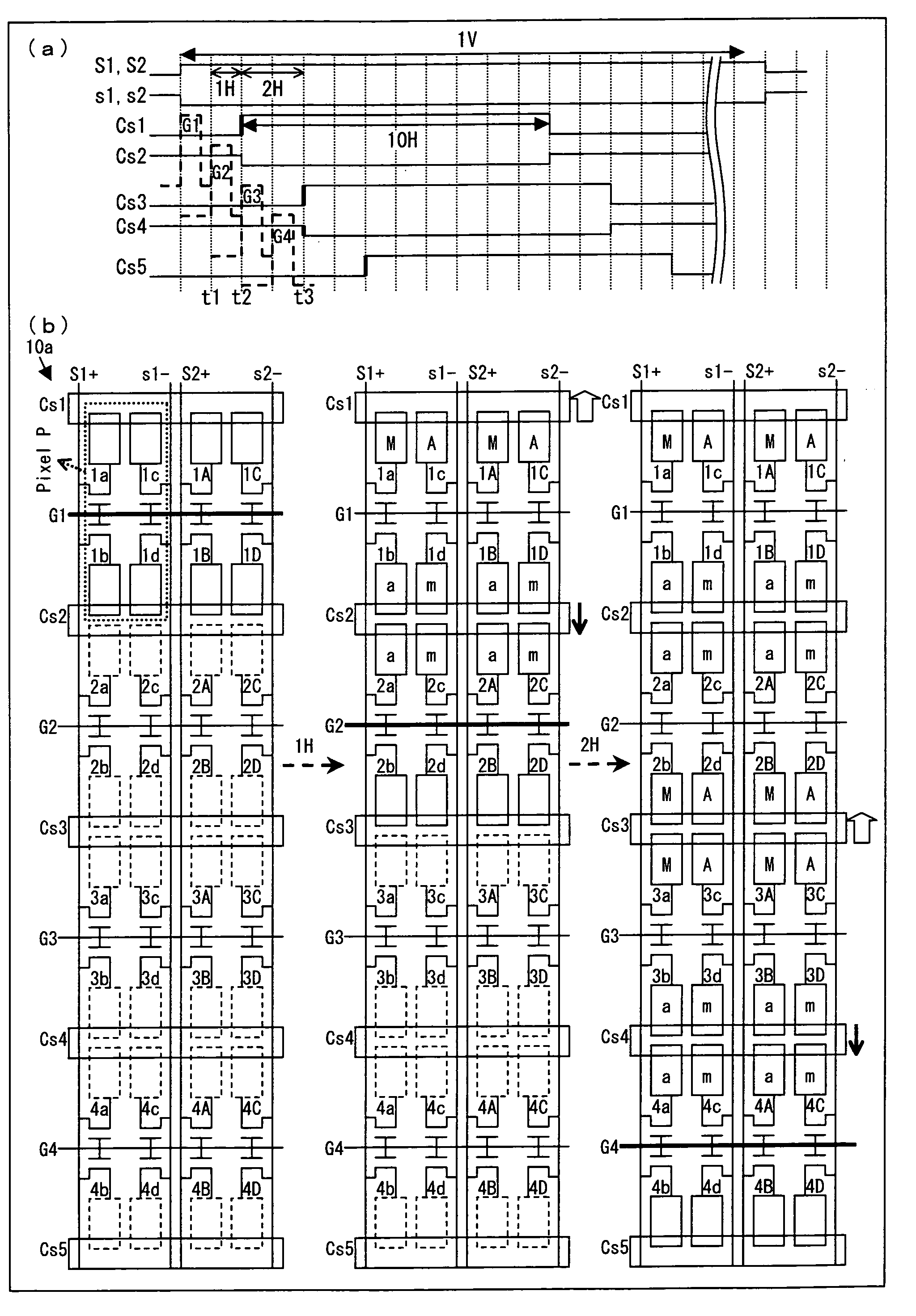
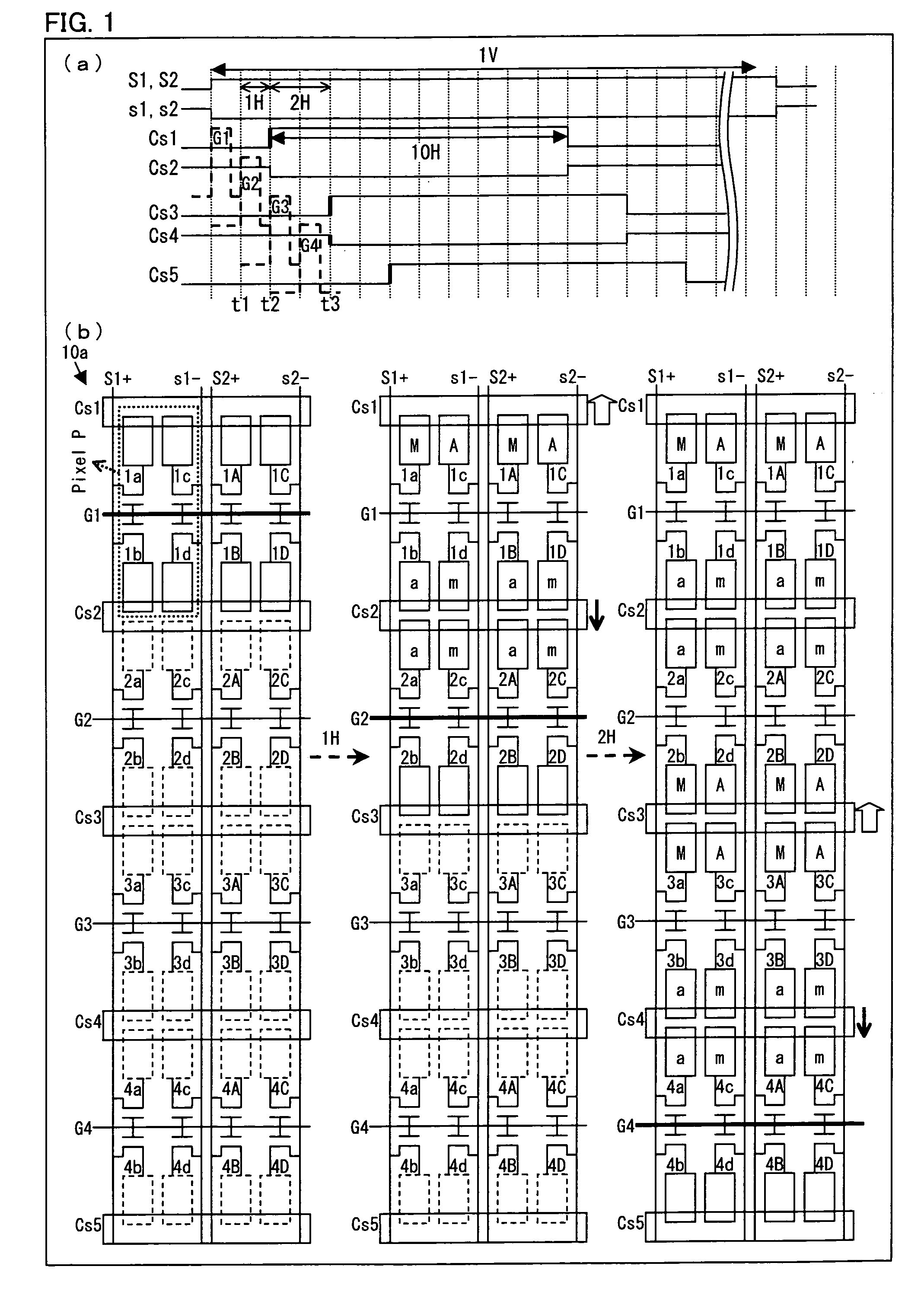
[0140]The following description discusses an embodiment of FIG. 1. (a) of FIG. 1 is a timing diagram illustrating how a display section of a liquid crystal display device of the present invention is driven. (b) of FIG. 1 is a view schematically illustrating a configuration of the display section and a process of how the display section is driven. The left side of (b) of FIG. 1 illustrates the display section at a timing t1 of (a) of FIG. 1. The center of (b) of FIG. 1 illustrates the display section at a timing t2 of (a) of FIG. 1. The right side of (b) of FIG. 1 illustrates the display section at a timing t3 of (a) of FIG. 1. As illustrated in (b) of FIG. 1, a display section 10a is so configured that (i) first and second data signal lines are provided correspondingly to each pixel array at its both side ends and (ii) each pixel includes four subpixels which are connected to identical one of the scanning signal lines. Each pixel is associated correspondingly with two storage capaci...

embodiment 2

[0209]The following description discusses a configuration of FIG. 26. (a) of FIG. 26 is a timing diagram illustrating how a display section of the liquid crystal display of the present invention is driven. (b) of FIG. 26 is a view schematically illustrating a configuration of the display section and a process of how the display section is driven. The left side of (b) of FIG. 26 illustrates the display section at a timing t1 of (a) of FIG. 26. The center of (b) of FIG. 26 illustrates the display section at a timing t2 of (a) of FIG. 26. The right side of (b) of FIG. 26 illustrates the display section at a timing t3 of (a) of FIG. 26. As illustrated in (b) of FIG. 26, a display section 10b is configured such that (i) first and second data signal lines are provided correspondingly to each pixel array at its both side ends and (ii) each pixel includes three subpixels which are connected to identical one of scanning signal lines. Each pixel is associated correspondingly with two storage ...


PUM


Abstract

At least one embodiment of the present invention provides a configuration in which: each pixel array is provided correspondingly with a first and second data signal lines; a pixel included in each pixel array includes four subpixels which are connected to an identical scanning signal line; the pixel is associated correspondingly with two storage capacitor wires; the two subpixels of the pixel define respective capacitances with one of the two storage capacitor wires; one of the two subpixels is connected to the first data signal line while the other one of the two subpixels is connected to the second data signal lien; the other two subpixels define respective capacitances with the other one of the two storage capacitor wires; and one of the other two subpixels is connected to the first data signal line while the other one of the other two subpixels is connected to the second data signal line. According to the configuration, it is possible to control four subpixels included in each pixel so that the four subpixels have respective different luminance levels. As such, it is possible to display a gray level by making use of the different luminance levels.

Description

TECHNICAL FIELD[0001]The present invention relates to (i) a liquid crystal display device employing a divided-pixel system, in which each pixel includes a plurality of subpixels, (ii) an active matrix substrate used in a liquid crystal display device employing the divided-pixel system, and (iii) a liquid crystal panel used in a liquid crystal display device employing the divided-pixel system.BACKGROUND ART[0002]Viewing angle dependence of a gamma characteristic is a difference between (i) a gamma characteristic of a liquid crystal display device as seen from the front and (ii) a gamma characteristic of the liquid crystal display device as seen at an angle. In order to improve the viewing angle dependence of the gamma characteristic on the liquid crystal display device, various solutions have been proposed. One of the solutions is a divided-pixel system (so-called multi-pixel technique), in which each pixel includes a plurality of subpixels (for example, refer to Patent Literature 1)...

Claims


Application Information

Patent Timeline
Patent Type & Authority Applications(United States)
IPC IPC(8): G09G3/36
CPCG02F1/136213G02F1/13624G02F1/136286G02F2001/134345G09G3/2074G09G3/3607G09G3/3648G09G2300/0426G09G2300/0447G09G2300/0876G09G2320/028G02F1/134345
Inventor TSUBATA, TOSHIHIDE
Owner SHARP KK
Why Eureka
Try Eureka