Liquid crystal display

a liquid crystal display and display technology, applied in the field of liquid crystal display, can solve the problems of display performance, front appears brighter, and the brightness difference between grayscales is very unclear, so as to improve the characteristics of liquid crystal displays, reduce the viewing angle dependence of characteristics, and display high quality

Active Publication Date: 2005-06-09
SHARP KK
View PDF19 Cites 212 Cited by
  • Summary
  • Abstract
  • Description
  • Claims
  • Application Information

AI Technical Summary

Benefits of technology

[0097] The first aspect of the present invention can reduce the viewing angle dependence of γ characteristics in a liquid crystal display. In particular, it can achieve extremely high display quality by improving γ characteristics of liquid crystal displays with a wide viewing angle such as MAV or ASV liquid crystal displays.
[0098] The second aspect of the present invention can reduce flickering on a liquid crystal display driven by alternating current. By combining the first and second aspects of the present invention, it is possible to provide a liquid crystal display with reduced flickering, improved viewing angle characteristics of y characteristics, and high quality display.
[0099] The third aspect of the present invention can increase the periods of oscillation of the voltages (oscillating voltages) applied to the storage capacitor counter electrodes in the liquid crystal display according to the second aspect. Thus, it is possible to provide a liquid crystal display which is suitable for improving viewing angle characteristics of a large or high-resolution liquid crystal display by dividing one pixel into two ormore sub-pixels and illuminating the sub-pixels at different brightness levels.
[0100] The fourth aspect of the present invention can supply oscillating voltages to the sub-pixels of adjacent pixels in the column direction using common storage capacitor lines (CS buslines) in addition to being able to increase the periods of oscillation of the voltages (oscillating voltages) applied to the storage capacitor counter electrodes as is the case with the third aspect. Consequently, the storage capacitor lines can also serve as black matrices (BM) if placed between pixels adjacent to each other in the column direction. Thus, the fourth aspect, which can omit the black matrices that need to be provided separately in the case of the liquid crystal display according to the third aspect as well as reduce the number of CS buslines compared to the third aspect, has the advantage of being able to increase the aperture ratio of pixels.

Problems solved by technology

On the other hand, it has problems with display performance, especially with viewing angle characteristics.
Consequently, even if an image clearly presents a plurality of grayscales from black to white when viewed from the front, brightness differences between grayscales appear very unclear when the image is viewed obliquely.
Besides, the phenomenon (so-called grayscale reversal) that a portion which appears dark when viewed from the front appears brighter when viewed obliquely also presents a problem.
Under circumstances where display quality of liquid crystal displays continues to be improved, a new problem with viewing angle characteristics have surfaced, namely, viewing angle dependence of γ characteristics, meaning that γ characteristics differ between when the display is viewed from the front and when the display is viewed obliquely.
This presents a problem, especially when displaying images such as photographs or displaying television broadcasts and the like.
On the other hand, it is more difficult to produce IPS panels which provide a high contrast ratio when viewed from the front with high productivity than MVA or ASM panels.

Method used


Image

  • Liquid crystal display
  • Liquid crystal display
  • Liquid crystal display

Examples


Embodiment Construction

[0158] Configuration and operation of liquid crystal displays according to embodiments in a first aspect of the present invention will be described below with reference to drawings.

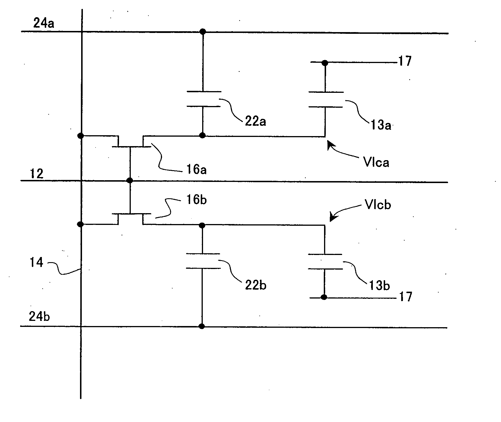
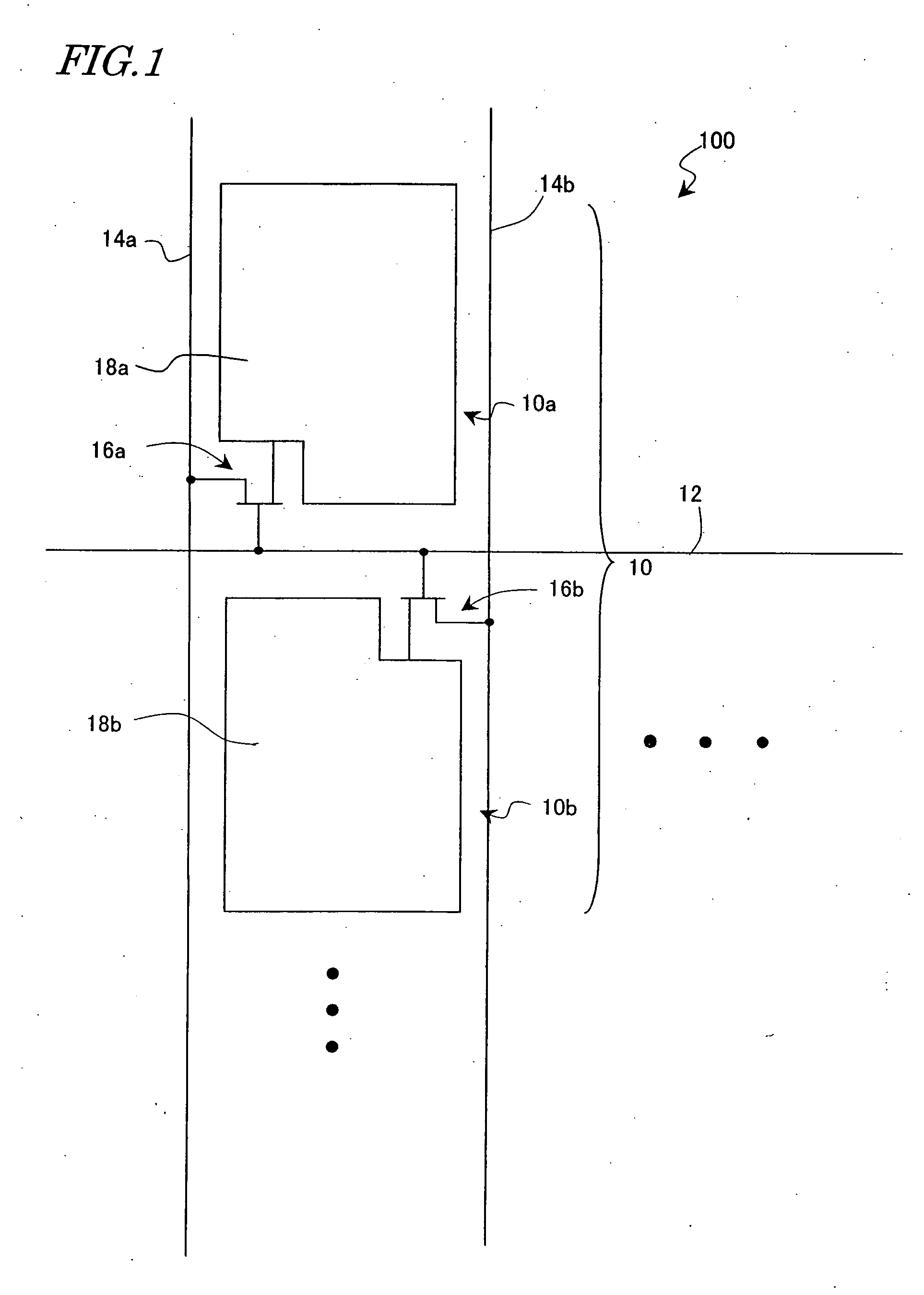
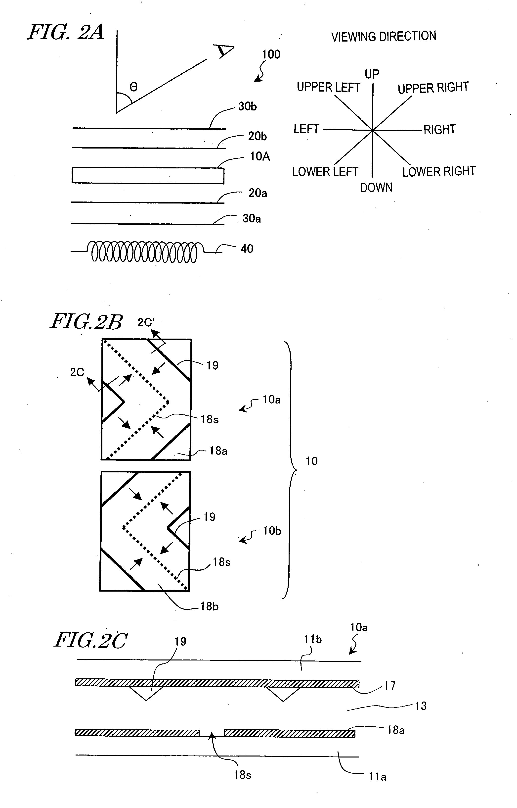
[0159] First, refer to FIGS. 1, 2A, 2B, and 2C. FIG. 1 is a diagram schematically showing an electrode arrangement in a pixel of a liquid crystal display 100 according to an embodiment of the present invention. FIG. 2A is a diagram schematically showing an overall configuration of the liquid crystal display 100, FIG. 2B is a diagram schematically showing an electrode structure in a pixel, FIG. 2C is a sectional view taken along a line 2C-2C′ in FIG. 2B. For the purpose of reference, an electrode arrangement in a pixel of a conventional liquid crystal display 100′, its electrode structure, and a sectional view taken along a line 3C-3C′ are shown schematically in FIGS. 3A, 3B, and 3C, respectively.

[0160] The liquid crystal display 100 according to this embodiment operates in normally black mode and compri...


PUM

PropertyMeasurementUnit
transmittanceaaaaaaaaaa
angleaaaaaaaaaa
threshold voltageaaaaaaaaaa

Abstract

A liquid crystal display of the invention includes a plurality of pixels each of which has a liquid crystal layer and a plurality of electrodes for applying a voltage to the liquid crystal layer and which are arranged in a matrix of rows and columns, wherein: each of the plurality of pixels has a first sub-pixel and a second sub-pixel which can apply mutually different voltages to the liquid crystal layer, where the first sub-pixel has a higher brightness than the second sub-pixel in certain gradations; the first sub-pixel and the second sub-pixel each has: a liquid crystal capacitor formed by a counter electrode and a sub-pixel electrode opposing the counter electrode via the liquid crystal layer, and a storage capacitor formed by a storage capacitor electrode connected electrically to the sub-pixel electrode, an insulating layer, and a storage capacitor counter electrode opposing the storage capacitor electrode via the insulating layer; the counter electrode is a single electrode shared by the first sub-pixel and the second sub-pixel, and the storage capacitor counter electrodes of the first sub-pixel and the second sub-pixel are electrically independent of each other; and the storage capacitor counter electrode of the first sub-pixel in any of the plurality of pixels and the storage capacitor counter electrode of the second sub-pixel of a pixel adjacent to any of the pixels in the column direction are electrically independent of each other.

Description

BACKGROUND OF THE INVENTION [0001] 1. Field of the Invention [0002] The present invention relates to a structure and / or drive method which can reduce viewing angle dependence of γ characteristics in a liquid crystal display. [0003] 2. Description of the Related Art [0004] Liquid crystal displays are flat-panel displays which have excellent features including high resolution, small thickness, light weight, and low power consumption. Their market size has expanded recently with improvements in display performance and production capacity as well as improvements in price competitiveness against other types of display device. [0005] Twisted nematic (TN) liquid crystal displays which have conventionally been in common use have liquid crystal molecules with positive dielectric anisotropy placed between upper and lower substrates in such a way that their long axis are oriented approximately parallel to substrate surfaces and twisted 90 degrees along the thickness of a liquid crystal layer. ...

Claims


Application Information

Patent Timeline
Patent Type & Authority Applications(United States)
IPC IPC(8): G02F1/133G02F1/1368G02F1/1343G02F1/1362G09G3/20G09G3/36
CPCG02F1/136213G02F1/13624G02F2001/134345G09G3/2074G09G3/3614G09G3/3648G09G2320/028G09G2300/0443G09G2300/0447G09G2300/0876G09G2320/0223G09G2320/0247G09G2320/0276G09G3/3655G02F1/134345G02F1/133G02F1/1343
Inventor SHIMOSHIKIRYOH, FUMIKAZU
Owner SHARP KK
Why Eureka
Try Eureka