
Optimized carrier aggregation for handover

Inactive Publication Date: 2013-01-24
ALCATEL LUCENT SAS
View PDF2 Cites 31 Cited by
  • Summary
  • Abstract
  • Description
  • Claims
  • Application Information

AI Technical Summary

Benefits of technology

This invention relates to a method to allow for efficient handovers of multiple wireless devices in a communication network. The invention uses a dedicated preamble to simplify the process of connecting to a new cell. This preamble allows for faster and more seamless handovers, while avoiding the need for additional signaling between the network and the handovers. The invention also allows for automatic activation of new aggregated component carriers without the need for separate MAC signaling, which improves the user experience during handovers.

Problems solved by technology

However, not all CCs may necessarily be release 8 / 9 compatible.

Method used


Image

  • Optimized carrier aggregation for handover
  • Optimized carrier aggregation for handover
  • Optimized carrier aggregation for handover

Examples


Embodiment Construction

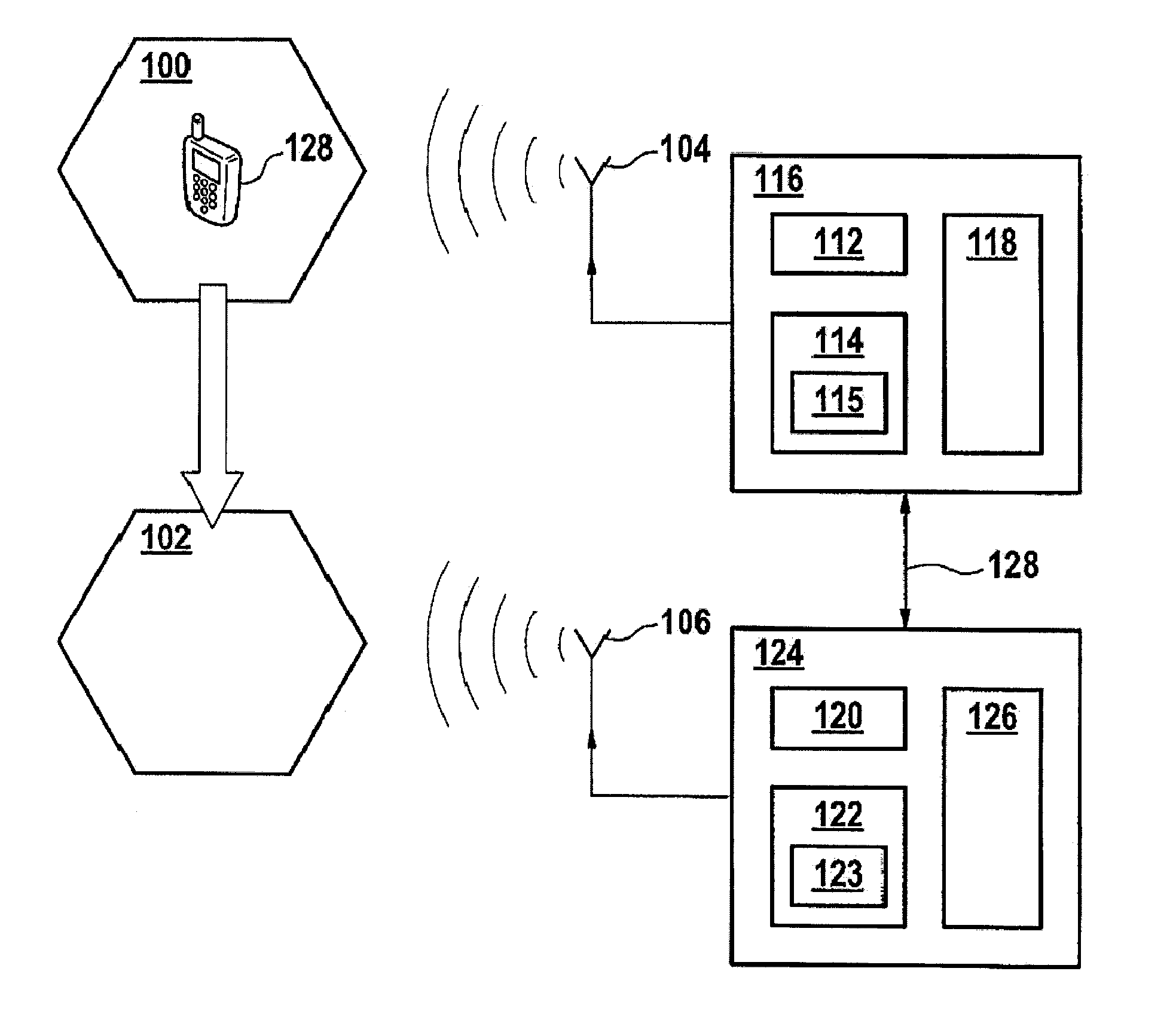
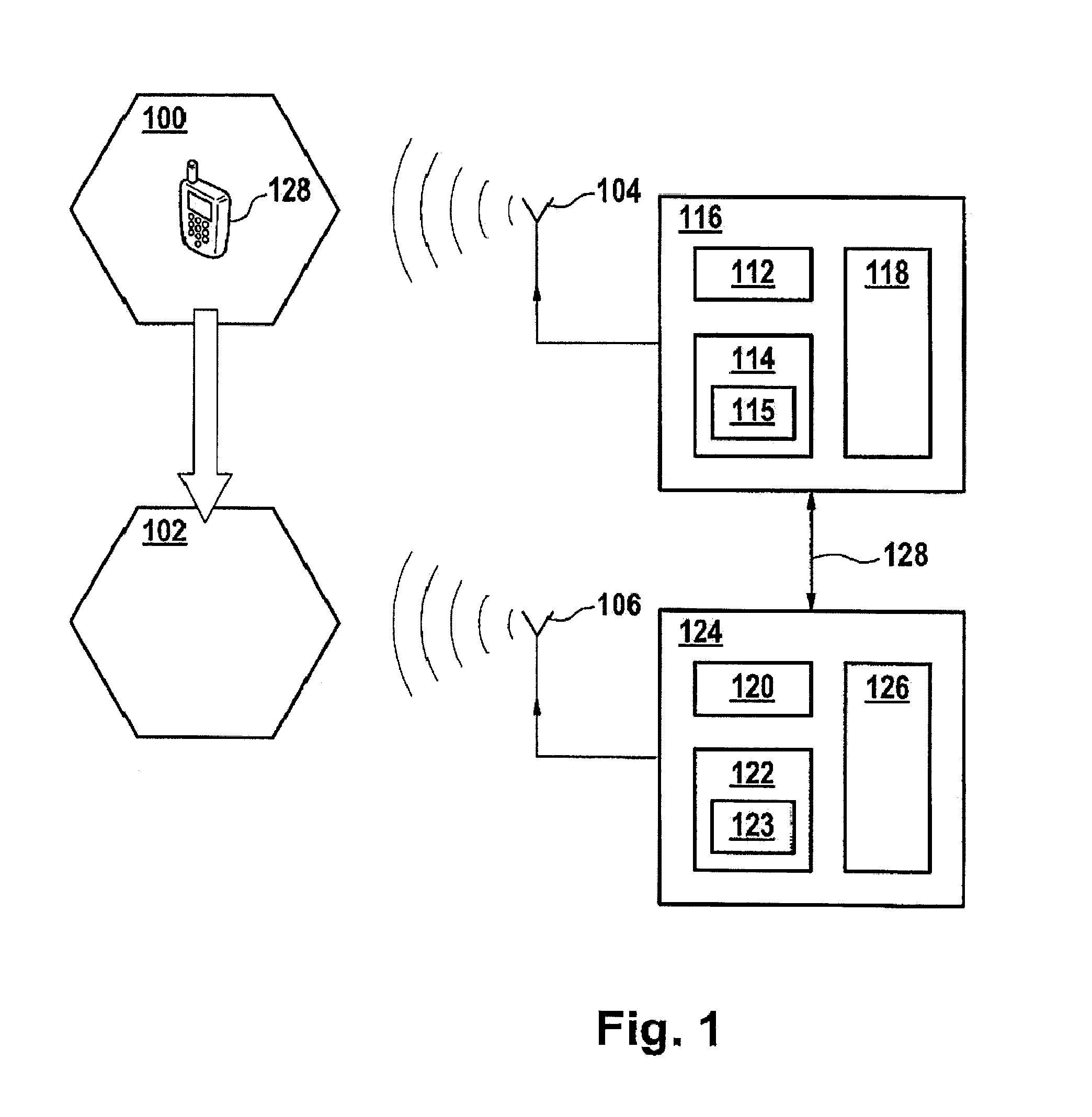
[0024]FIG. 1 illustrates a block diagram of a wireless communication network. It has to be noted, that only features are shown here which are relevant for the present invention.

[0025]The network illustrated in FIG. 1 is for example a UMTS terrestrial radio access network (UTRAN) based upon a 3GPP radio access network specification. The communication network comprises two eNodeBs 116 and 124 and a user equipment UE 128. As illustrated in FIG. 1, the UE 128 is currently spatially located in a source cell 100 served by the eNodeB 116.

[0026]Serving by the eNodeB 116 is performed via the antenna 104 which provides network coverage with respect to the source cell 100.

[0027]The eNodeB 116 comprises a processor 112, as well as a memory 114. The memory 114 comprises a module 115 comprising computer executable instructions executable by the processor 112. These instructions may comprise any instructions to perform the method as described above.

[0028]Further, the eNodeB 116 comprises an interf...


PUM


Abstract

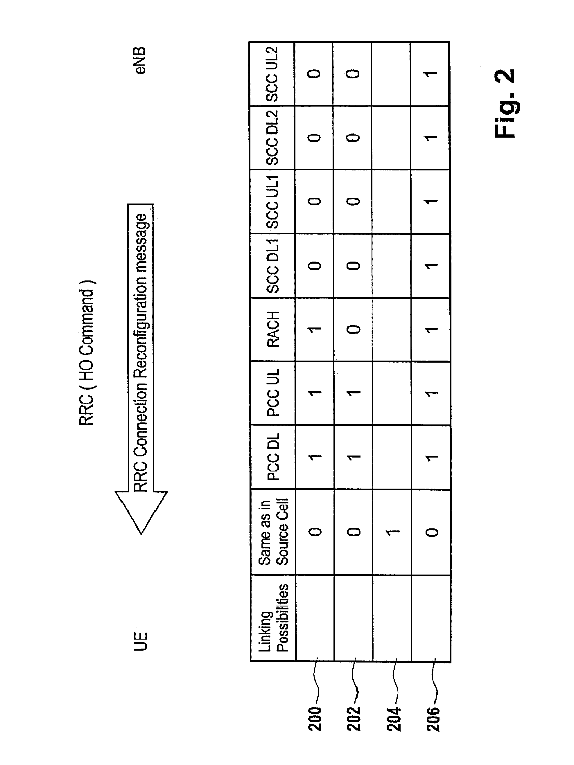
The invention relates to a method of performing a handover of a user equipment (128) from a source cell (100) to a target cell (102), wherein the user equipment (128) is adapted for receiving and / or transmitting data simultaneously on two or more aggregated component carriers, the method comprising receiving an RRC connection reconfiguration message from the source cell (100) on the random access channel of the source cell (100), said message comprising linking information, said linking information indicating one of the aggregated component carriers for the uplink of the target cell (102) and one of the aggregated component carriers for the downlink of the target cell (102).

Description

FIELD OF THE INVENTION[0001]The invention relates to a method of performing a handover of a user equipment from a source cell to a target cell, a user equipment, a method of performing a handover by a base station, a base station, as well as a computer program product.BACKGROUND AND RELATED ART[0002]Currently, UMTS (universal mobile telecommunications systems) networks are worldwide being upgraded in order to provide data to user equipments (EUs) at high data rates. In order to ensure the competitiveness of UMTS for the next couple of years and beyond, concepts for UMTS long term evolution (LTE) have been investigated. The objective is a high data rate, low latency and packet optimized radio access technology.[0003]A UMTS network constitutes the third generation (3G) of cellular wireless networks. Third generation partnership (3GPP) is working on establishing standards for multimedia services.[0004]An LTE advanced terminal, i.e. a user equipment (UE) can be jointly scheduled on mult...

Claims


Application Information

Patent Timeline
IPC IPC(8): H04W36/00
CPCH04W36/28H04W36/08H04W36/0069
Inventor AYDIN, OSMAN
Owner ALCATEL LUCENT SAS
Learn More