Coupling mechanism for a drive train of a hair cutting appliance

a technology of coupling linkage and drive train, which is applied in the direction of metal working apparatus, etc., can solve the problems of increasing noise level, certain risk of heat generation and related wear, and the respective driving joints of the angular offset compensation drive train are prone to wear, so as to improve the operating performance of the appliance, reduce noise and/or vibration, and improve the effect of user experien

Active Publication Date: 2019-10-22
KONINKLJIJKE PHILIPS NV
View PDF17 Cites 10 Cited by
  • Summary
  • Abstract
  • Description
  • Claims
  • Application Information

AI Technical Summary

Benefits of technology

[0008]It is therefore an object of the present disclosure to provide a drive train, particularly a coupling linkage for a drive train of a hair cutting appliance that may enhance the operating performance of the appliance and contributes to a pleasant user experience. Furthermore, it is desired to provide a hair cutting appliance fitted with a respective drive train. It is particularly desired that the drive train enables hair cutting operation at a significantly reduced noise and / or vibration level. More particularly, it is desired that the drive train is arranged in a hard-wearing fashion. It would be further preferred to diminish unpleasant emissions that may emerge from a drive train, for instance running noises and vibration emissions. Preferably, the drive train, particularly the coupling linkage thereof is arranged for angular offset compensation. Furthermore, the coupling linkage is preferably easy-to-assemble and easy-to-manufacture.
[0019]In one embodiment of the coupling linkage, a plurality of circumferentially arranged deflectable compensation elements is provided, wherein preferably three deflectable compensation elements are provided, and wherein the compensation elements are arranged to apply a centering compensation force to the male connector and the female connector. The compensation elements may be evenly distributed at the circumference of either the male connector or the female connector. In case three or more compensation elements are provided, a self-centering alignment may be achieved more easily.
[0022]Preferably, the at least one compensation element may exert a force on the joint section which maintains the engagement state of the male connector and the female connector. Consequently, the compensation element may further act as a loss-proof or loss-prevention element. This may further simplify the manufacturing process.
[0036]In yet another embodiment of the coupling linkage, a plurality of compensation elements is provided, wherein the male connector and the female connector engage one another in a preloaded fashion. Preferably, the male connector and the female connector engage one another in a self-centered fashion. A relatively low bias or preloading is required for sufficiently reduce the noise level and / or the vibration level of the drive train. Assuming that an angular offset is present between the male connector and the female connector, a more or less constant (axial) sliding movement between involved contact surfaces is present when a rotational movement is transferred via the respective joint. It is therefore preferred that only a limited preloading is present so as to avoid heat generation and associated operation impairments (huge friction, etc.). Consequently, excessive power consumption and an unpleasant temperature increase may be avoided. For instance, the preload level may be in the range of 0.1 N (Newton) to 1.0 N, preferably in the range of about 0.15 N to about 0.3 N, when the compensation elements and the neighboring assembly parts are in an aged state. So as to achieve the preloaded between the male connector and the female connector, the compensation elements may be formed in such a way that the male connector and the female connector may be attached to one another in an at least slight press-fit fashion.
[0037]At least in some embodiments in accordance with the present disclosure, the need of grease or a similar lubricant may be dispensed with. Nevertheless, in some embodiments, grease or another appropriate lubricant may be added so as to avoid excessive wear, and to reduce friction related to the relative sliding motion between the involved components. At least a reduced amount of grease or another suitable lubricant is required to achieve a smooth running performance. The less lubricant is used, the better the drive train can sustain wet cleansing. Further, the less lubricant is used, the fewer dirt and debris may adhere or stick to the drive train.
[0042]In accordance with the above embodiment, two compensation joints are provided which improves the ability of the coupling linkage to compensate even larger angular offsets. For instance, an overall offset δ (delta) between the driving shaft and the output shaft may be split into two partial offset angles α (alpha) and β (beta), wherein the first joint handles the offset angle α, and wherein the second joint handles the offset angle β. Consequently, an even further convex shape of the hair cutting appliance may be provided. Needless to say, one or both of the joints may be arranged in accordance with the above-described embodiments and aspects.

Problems solved by technology

Further, it has been observed that, in certain applications, respective driving joints of angular offset compensation drive trains are prone to wear, depending on actual tolerance conditions.
If only tight fit or press fit tolerances are present, there is a certain risk of heat generation and related wear.
In case too much play is provided and large clearances are present between mating parts, an increase of the noise level may result.
This may pose further challenges to the drive train design for hair cutting appliances.

Method used


Image

  • Coupling mechanism for a drive train of a hair cutting appliance
  • Coupling mechanism for a drive train of a hair cutting appliance
  • Coupling mechanism for a drive train of a hair cutting appliance

Examples


Embodiment Construction

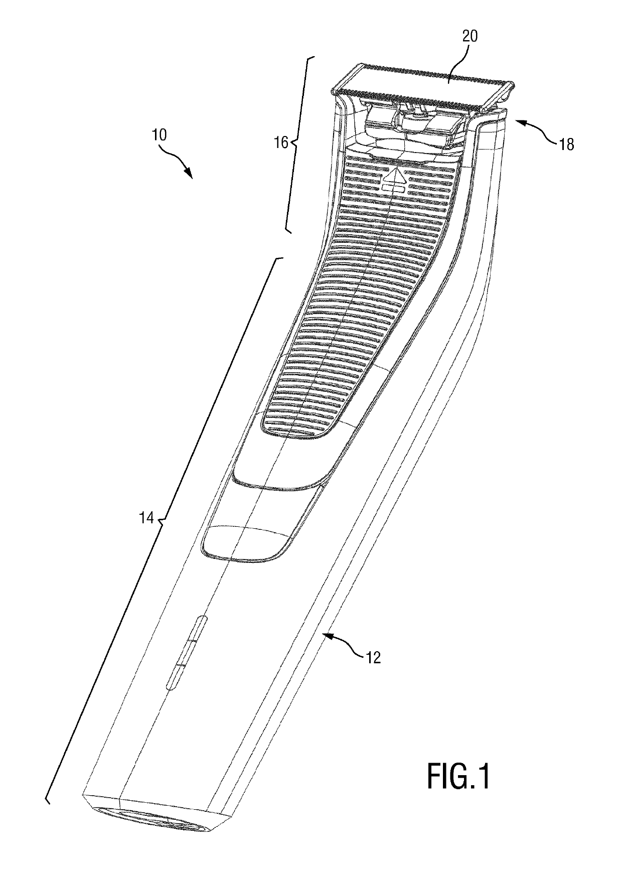
[0064]FIG. 1 schematically illustrates a hair cutting appliance 10, particularly an electric hair cutting appliance 10. The hair cutting appliance 10 in accordance with FIG. 1 includes a housing 12 which is arranged to house a motor for driving the hair cutting appliance 10. The housing 12 may further house a battery, for instance a rechargeable battery. However, in some embodiments, the hair cutting appliance 10 may be provided with a power cable for connecting a power supply. A power supply connector may be provided in addition or in the alternative to an (internal) electric battery. The housing 12 may further comprise operator controls, for instance switches, buttons, LEDs, and such like.

[0065]As indicated in FIG. 1 by brackets (reference numerals 14, 16), the housing 12 may comprise a main portion 14 and a neck portion 16. Further, a cutting head 18 is provided which is associated to the neck portion 16, at least in the mounted state. As shown in FIG. 1 in an illustrative, non-l...


PUM


Abstract

A self-aligning coupling linkage for a drive train, of a hair cutting appliance having a driving shaft and a non-aligning output shaft, includes a joint section having first and second connector portions that are configured to engage one another for torque transmission. The first second connector portions define a male connector having an external polygonal profile, viewed in a cross-sectional plane perpendicular to a longitudinal axis, and a female connector having an internal engagement profile. The male and female connectors are arranged in a self-aligning fashion for angular offset compensation, where wherein at least one of the male and female connectors is provided with at least one circumferentially arranged deflectable compensation element configured to urge the male and female connectors towards a centered alignment.

Description

[0001]This application is the U.S. National Phase application under 35 U.S.C. § 371 of International Application No. PCT / EP2016 / 082500, filed on Dec. 22, 2016, which claims the benefit of International Application No. 15202049.1 filed on Dec. 22, 2015. These applications are hereby incorporated by reference herein.FIELD OF THE INVENTION[0002]The present disclosure relates to a hair cutting appliance, particularly to an electrically operated hair cutting appliance, and more particularly to a coupling linkage mechanism for a drive train of a hair cutting appliance which is arranged to compensate an angular offset between a driving shaft and a non-aligning output shaft which is arranged at an angular offset with respect to the driving shaft.BACKGROUND OF THE INVENTION[0003]WO 2015 / 158681 A1 discloses a hair cutting appliance, particularly an electrically operable hair cutting appliance, said hair cutting appliance comprising a housing, a cutting head attached to said housing, and a dri...

Claims


Application Information

Patent Timeline
Patent Type & Authority Patents(United States)
IPC IPC(8): B26B19/28B26B19/38B26B19/06
CPCB26B19/386B26B19/28B26B19/063
Inventor EIJKELKAMP, MARCUS FRANCISCUSTACK, JOHANNES WILLEMDE GOEIJ, GEERT WILLEM
Owner KONINKLJIJKE PHILIPS NV
Why Eureka
Try Eureka