Vehicle instrument panel

a technology for instrument panels and vehicles, applied in vehicle cleaning, vehicle heating/cooling devices, vehicle components, etc., can solve problems such as condensation on the front face of instrument panel members, and achieve the effect of suppressing condensation

Inactive Publication Date: 2013-01-24
TOYOTA JIDOSHA KK
View PDF5 Cites 6 Cited by
  • Summary
  • Abstract
  • Description
  • Claims
  • Application Information

AI Technical Summary

Benefits of technology

[0032]As described above, according to the present invention, condensation can be suppressed from developing on the front face of the instrument panel main body.

Problems solved by technology

There is therefore concern of condensation developing on a front face of the instrument panel member when cooled air passes through inside the duct.

Method used


Image

  • Vehicle instrument panel
  • Vehicle instrument panel
  • Vehicle instrument panel

Examples


first exemplary embodiment

[0046]Explanation first follows regarding a first exemplary embodiment of the present invention.

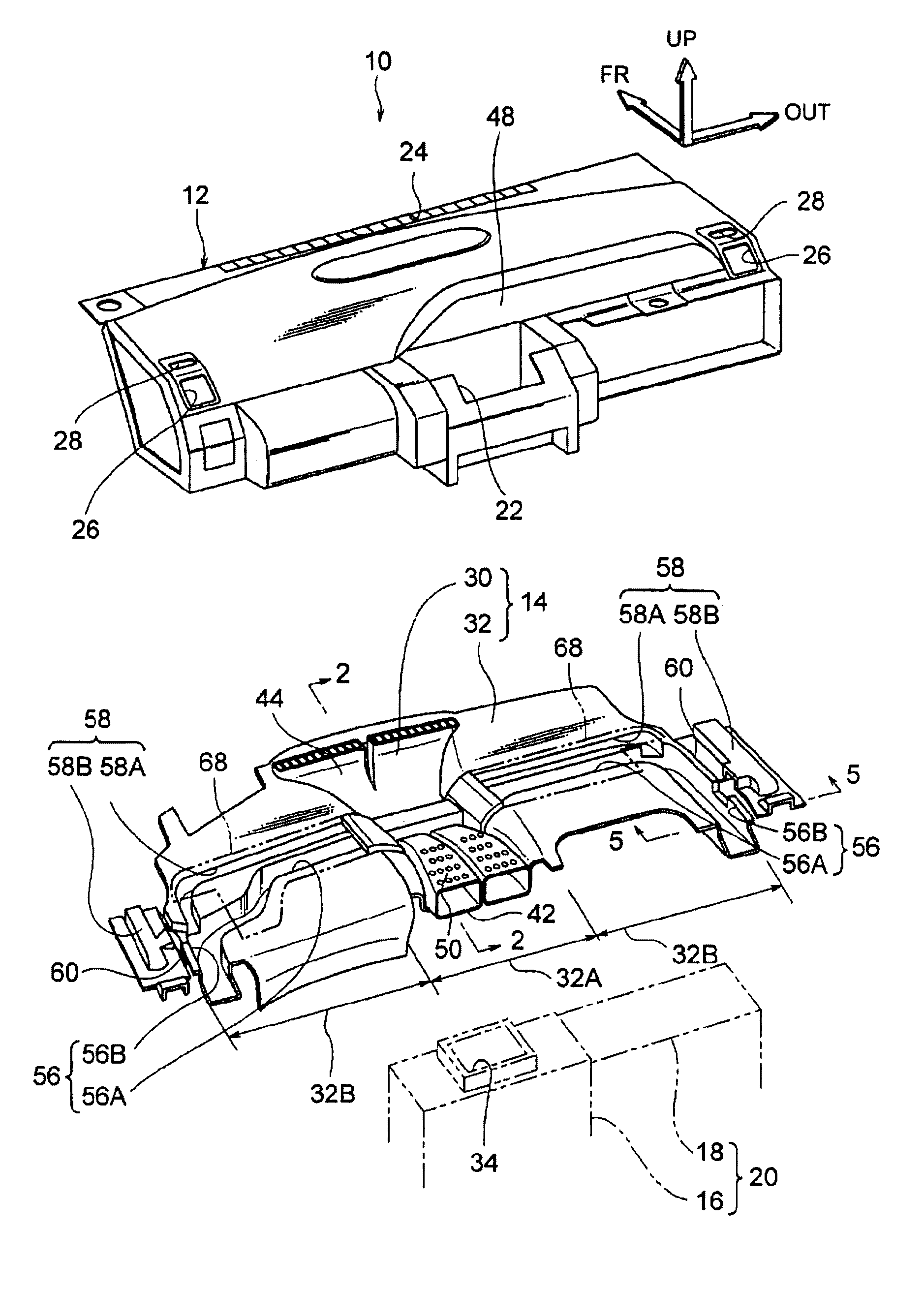
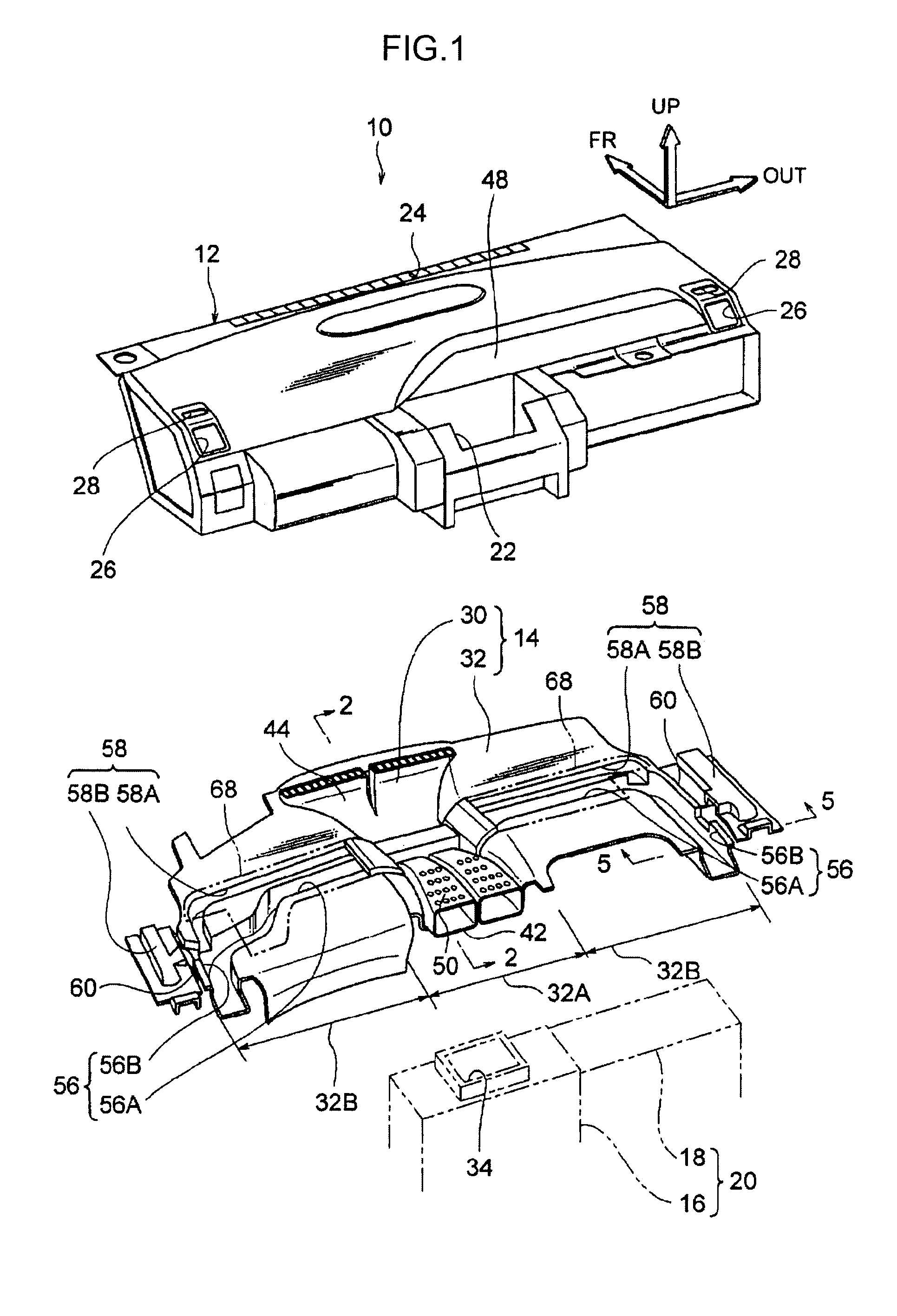
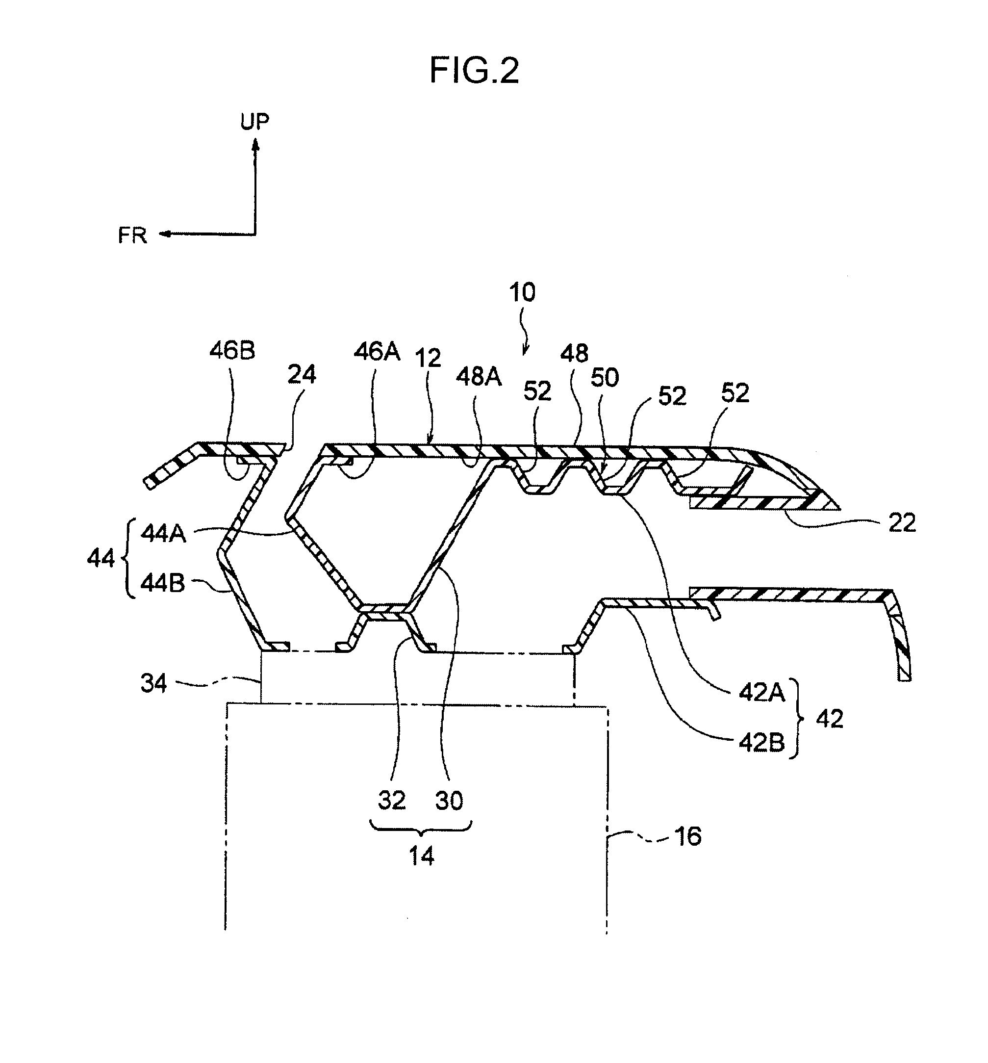
[0047]In each of the drawings, an arrow UP, an arrow FR and an arrow OUT respectively indicate a vehicle top-bottom direction top side, a vehicle front-rear direction front side, and a vehicle width direction outside (right side), as appropriate.

[0048]As shown in FIG. 1, an instrument panel 10 serving as a vehicle instrument panel of the first exemplary embodiment of the present invention includes an instrument panel main body 12 and a duct configuring member 14.

[0049]The instrument panel main body 12 is manufactured from a resin and is attached to in-panel reinforcement that spans across between left and right front pillars, not shown in the drawings. The instrument panel main body 12 is provided inside a vehicle compartment, and covers a vehicle structural body 20 formed from devices installed to the vehicle, such as an air conditioner 16 and an airbag device 18.

[0050]A center air condi...

second exemplary embodiment

[0098]Explanation follows regarding a second exemplary embodiment of the present invention.

[0099]As shown in FIG. 8, an instrument panel 90 serving as a vehicle instrument panel according to a second exemplary embodiment of the present invention is equipped with an instrument panel main body 12 and a duct configuring member 94.

[0100]The instrument panel main body 12 is configured similarly to that of the first exemplary embodiment of the present invention. A right side panel section 72 and a left side panel section 74 of the instrument panel main body 12 are respectively reinforced by reinforcement sections 120, 122, described later.

[0101]The duct configuring member 94 is manufactured from a resin and provided between the instrument panel main body 12 and a vehicle structural body 20. The duct configuring member 94 is configured by a first panel 100 and a second panel 102 disposed at the vehicle top-bottom direction bottom side.

[0102]The first panel 100 and the second panel 102 are ...

third exemplary embodiment

[0136]Explanation follows regarding a third exemplary embodiment of the present invention.

[0137]As shown in FIG. 12, an instrument panel 190 serving as a vehicle instrument panel according to a third exemplary embodiment of the present invention is equipped with an instrument panel main body 12 and a duct configuring member 194.

[0138]The instrument panel main body 12 is configured similarly to in the first and the second exemplary embodiments of the present invention.

[0139]The duct configuring member 194 is configured by a first panel 200 disposed at the vehicle top-bottom direction top side and a second panel 202 disposed at the vehicle top-bottom direction bottom side. The external shape of the first panel 200 is smaller than the external shape of the second panel 202.

[0140]The first panel 200 and the second panel 202 are configured similarly to in the second exemplary embodiment with center air conditioning ducts 212, center defroster ducts 214, side air conditioning ducts 216 an...


PUM


Abstract

Condensation is suppressed from developing on a front face of an instrument panel main body. A instrument panel of the present invention is configured including: an instrument panel main body formed with a center air conditioning outlet and a center defroster outlet; a first panel that is joined to the instrument panel main body and is formed with a top side wall section that configures the vehicle top-bottom direction top side of a center air conditioning duct and a first wall section that configures part of a center defroster duct; and a second panel that is joined to the instrument panel main body and is formed with a bottom side wall section that configures the center air conditioning duct in combination with the top side wall section and a second wall section that configures the center defroster duct in combination with the first wall section.

Description

TECHNICAL FIELD[0001]The present invention relates to a vehicle instrument panel.BACKGROUND ART[0002]Known vehicle instrument panels are disclosed for example in following documents such as Japanese Patent Application Laid-Open (JP-A) No. 10-250414, JP-A No. 8-268041, JP-A No. 7-52683, JP-A No. 8-80762, JP-A No. 2002-87114, and JP-A No. 2004-299480. In an example described in JP-A No. 10-250414, a first panel member and a second panel member are disposed at the back side of an instrument panel member. The first panel member and the second panel member configure a nozzle section that is in communication with a defroster outlet formed in the instrument panel member. The first panel member, in combination with the instrument panel member, configures a duct that is in communication with an outlet member provided to the instrument panel member.SUMMARY OF INVENTIONTechnical Subject[0003]However, in the example of JP-A No. 10-250414, the instrument panel member configures part of a duct th...

Claims


Application Information

Patent Timeline
Patent Type & Authority Applications(United States)
IPC IPC(8): B60S1/54B60H1/24
CPCB60H1/00564B60H1/0055B60H1/242
Inventor NIWA, TAKASHIYAMAZAKI, YASUNOBUKONDO, TOTU
Owner TOYOTA JIDOSHA KK
Why Eureka
Try Eureka