
Apparatus and Method of Use for a PVC Composite Mattress Foundation

a technology of pvc and mattress support, which is applied in the direction of bedsofas, seating furniture, bedstands, etc., can solve the problems of insufficient strength of steel bedframes, waste of materials and increased costs, and inability to meet the needs of users, so as to reduce the amount of materials used and eliminate extra fastening hardware

Inactive Publication Date: 2013-01-31
WESTECH BUILDING PRODS
View PDF13 Cites 16 Cited by
  • Summary
  • Abstract
  • Description
  • Claims
  • Application Information

AI Technical Summary

Benefits of technology

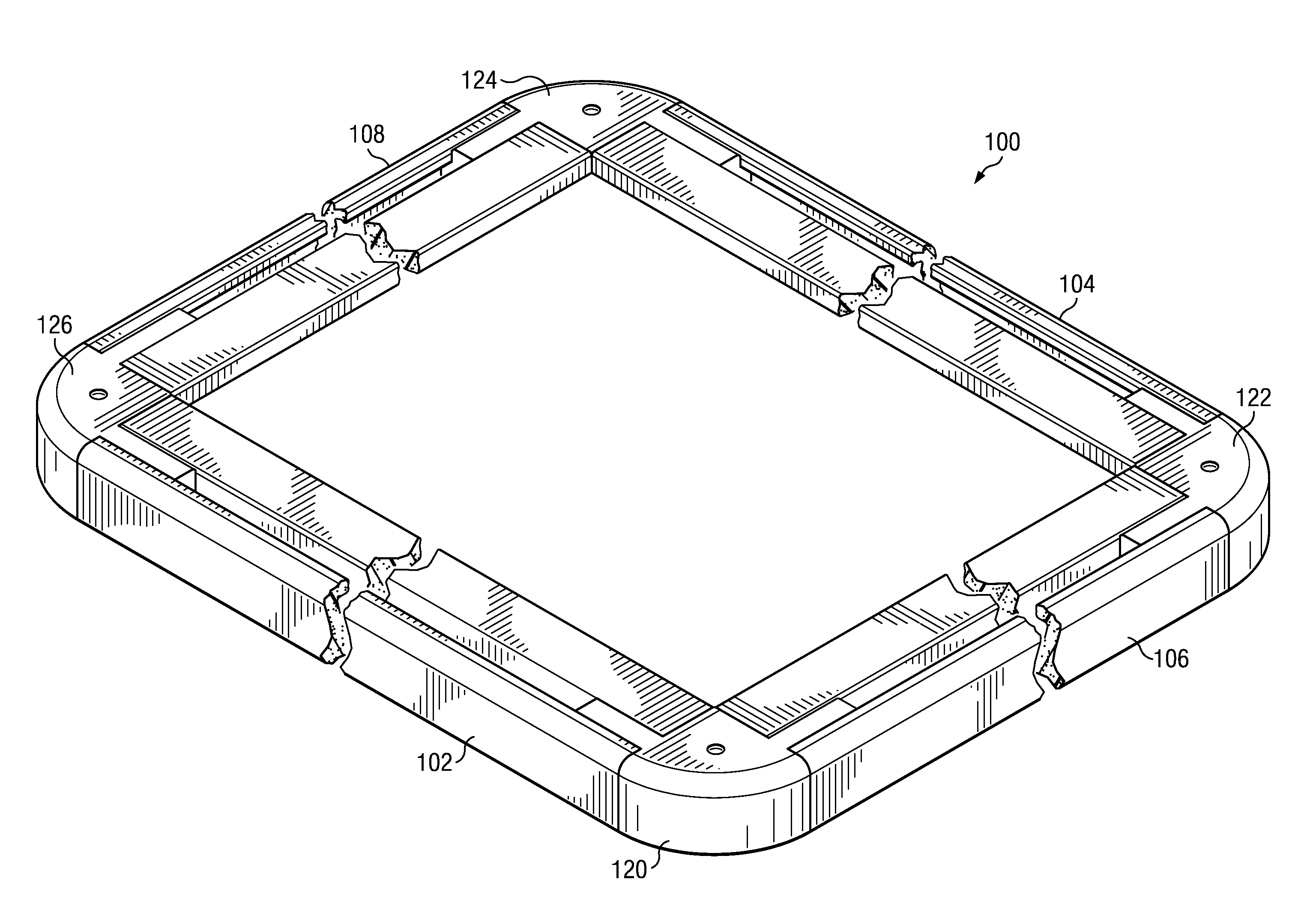
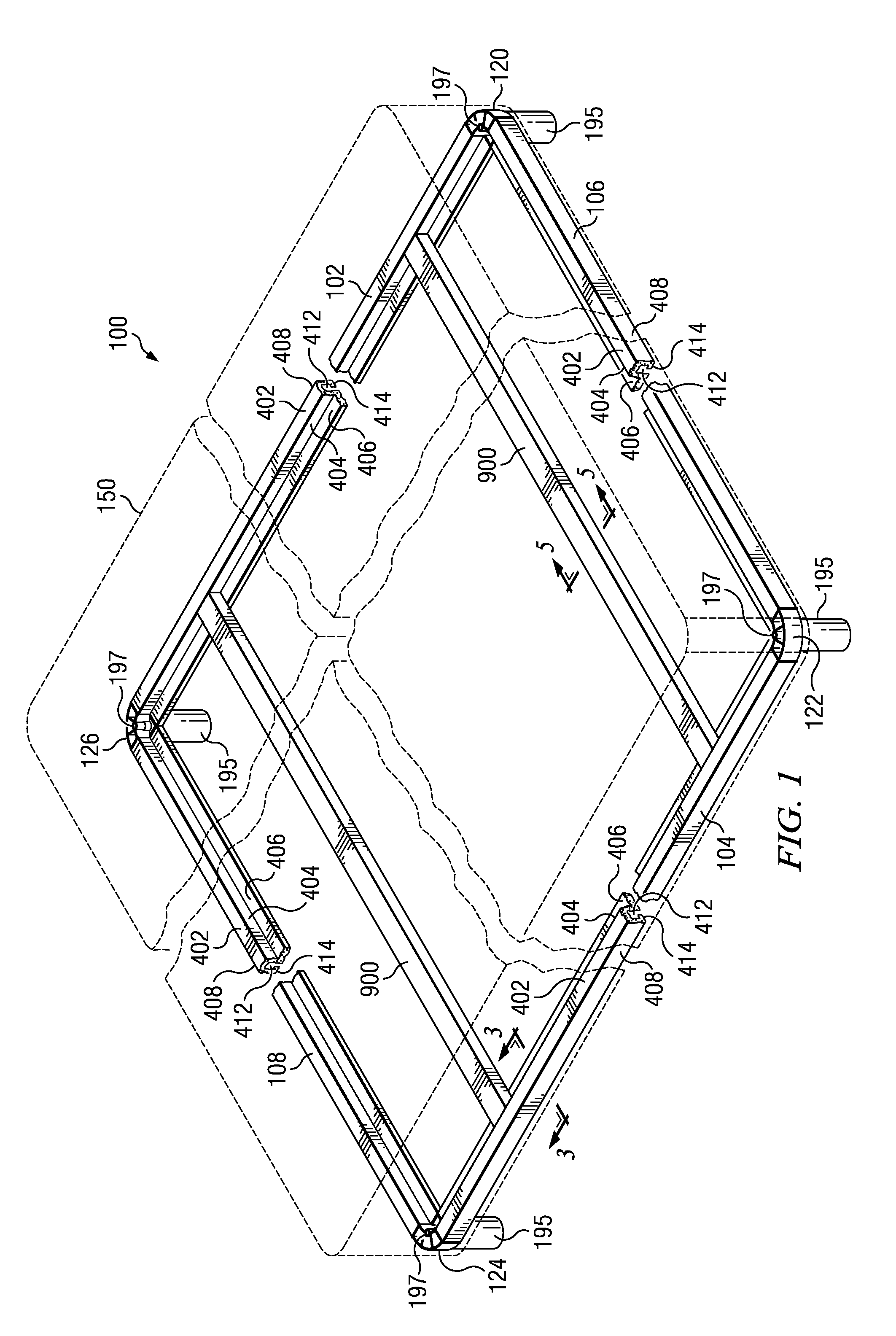
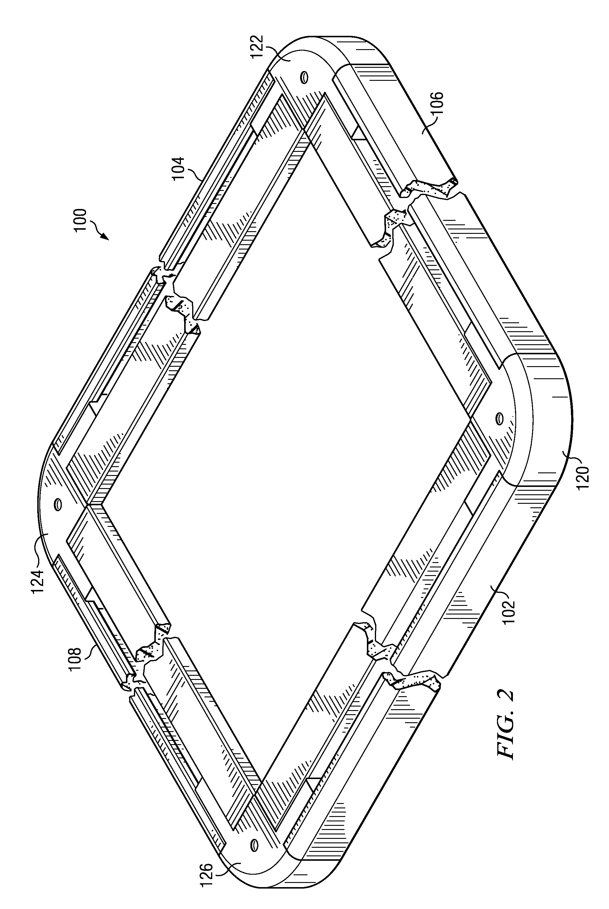
The invention is a mattress frame made of lightweight, durable, and flexible materials that is designed to minimize the use of materials and eliminate extra fastening hardware. The frame is made up of two pairs of side rails and two pairs of end rails that are connected through four end caps. The side rails and end rails have a unique cross-section shape made up of five sections surrounding a slot. The end caps are semi-circular and have tabs for insertion into the slots. The frame also includes encapsulated steel ribs. The frame can be raised by attaching feet to the end caps to eliminate the need for a bed frame.

Problems solved by technology

However, the rejection rate of the wood used to manufacture a typical mattress foundation can be as high as 15% due to natural faults in the wood leading to unacceptable amounts of waste and increased cost.
In the use of the steel bedframes of the past, a principle problem is that they are noisy.
Steel bedframes are fastened with rivets or adjustable screws that often produce squeaks.
Further, the plastic bedframes of the prior art, while potentially less noisy, lack the strength of steel bedframes, and can often collapse.
The Cretsinger device incorporates many intricate parts which complicate the manufacturing process and uses unnecessary amounts of material.
The Petruzella device is not easily re-configurable and does not support a mattress as it is the mattress itself.
Further, the Sheehy device has no steel reinforcement members.

Method used


Image

  • Apparatus and Method of Use for a PVC Composite Mattress Foundation
  • Apparatus and Method of Use for a PVC Composite Mattress Foundation
  • Apparatus and Method of Use for a PVC Composite Mattress Foundation

Examples


Embodiment Construction

[0029]In the descriptions that follow, like parts are marked throughout the specification and drawings with the same numerals, respectively. The drawing figures are not necessarily drawn to scale and certain figures may be shown in exaggerated or generalized form in the interest of clarity and conciseness.

[0030]FIG. 1 shows mattress frame 100 as would be incorporated within box springs 150 (shown in shadow) where box springs 150 would include springs and fabric cover as is common in the art. A set of feet 195 is included to raise the mattress frame when in use.

[0031]Referring to FIGS. 1 and 2, mattress frame 100 is comprised of a pair of side rails 102 and 104 connected to a pair of end rails 106 and 108 via end caps 120, 122, 124, and 126. In the preferred embodiment, the side rails and end rails are made of an extruded polyvinyl chloride (PVC) plastic. Other lightweight, flexible plastics will suffice. In the preferred embodiment, the end caps are made of a fiber reinforced nylon ...


PUM


Abstract

A lightweight and durable mattress foundation. The apparatus includes a first tier of side rails connected to a first tier of end rails via four end caps and a second tier of side rails connected to a second tier of end rails where the first tier is connected to the second tier via a plurality of standoffs. The side rails and the end rails can vary in length and include strengthening ribs. The first tier side and end rails have a unique cross-section made up of five sections surrounding a slot. The second tier side and end rails have a different unique cross-section. The end caps each include tabs for insertion into the slots of the side and end rails. Slats having a U-shaped cross-section and including strengthening ribs extend from side rail to side rail and / or from end rail to end rail. An alternate embodiment includes feet.

Description

CROSS-REFERENCE TO RELATED APPLICATIONS[0001]This application is a Continuation-In-Part claiming priority benefit from U.S. patent application Ser. No. 13 / 136,197, filed Jul. 26, 2011, entitled “Apparatus and Method of Use for a PVC Composite Mattress Frame.”FIELD OF THE INVENTION[0002]The present invention relates generally to bed structures. In particular, the invention relates to a lightweight and high strength extruded polyvinyl chloride (PVC) composite mattress support apparatus.BACKGROUND OF THE INVENTION[0003]A mattress frame, commonly known as a set of box springs, is a type of bed base typically consisting of a sturdy wooden frame covered in fabric, and containing springs. In use, the mattress frame or box spring is placed on a metal bed frame which supports the mattress frame and acts as a stand to raise the bed frame to a desirable height. The mattress frame supports a mattress. The bed frame, mattress frame and mattress make up a standard bed structure. Structural suppor...

Claims


Application Information

Patent Timeline
Patent Type & Authority Applications(United States)
IPC IPC(8): A47C19/02
CPCA47C19/021A47C19/025A47C19/024
Inventor SYROWITZ, GLENNSOUTHGATE, EDGAR A.
Owner WESTECH BUILDING PRODS
Learn More