Rotor balancing method

a rotor and rotor technology, applied in the direction of machines/engines, liquid fuel engines, instruments, etc., can solve the problems of increasing the rotor may then be subject to vibration, and the overall weight of the disc may increase, so as to reduce the computational complexity of the method, reduce the amount of time required, and reduce the cost of the computer

Active Publication Date: 2015-11-10
ROLLS ROYCE PLC
View PDF13 Cites 6 Cited by
  • Summary
  • Abstract
  • Description
  • Claims
  • Application Information

AI Technical Summary

Benefits of technology

[0018]The invention therefore provides a balancing method in which the amount of material added to the rotor is minimised, which in turn reduces the overall mass of the rotor and reduces the tensile load on the rotor in use, while also precluding or reducing the requirement for applying a series of trial weights to the physical rotor. The invention relies on the realisation that the use of a material deposition process enables finer control over the location and mass of the balance mass, which can be determined by simulation of the rotor.
[0022]The method may therefore ensure that the smallest amount of mass is added to the rotor to obtain the predetermined balance state of the rotor, while ensuring that the tensile loads on the rotor do not exceed a predetermined amount, or are minimised.
[0024]The method may therefore ensure that the smallest tensile load in use is exerted on the rotor by the mass while maintaining the balance mass below a predetermined maximum, and ensuring that the rotor is balanced to within predetermined limits. Different embodiments of the invention can therefore determine an optimised mass and location on the basis of either lowest mass or lowest stress, or a compromise between the two.
[0025]The one or more balance zones may be identified on the basis of areas of the rotor having one or more of a maximum predicted stress in use, a maximum likelihood of crack propagation following material deposition, minimum accessibility requirements, minimum load tolerance, minimum damage tolerance and maximum expected cycle fatigue.
[0026]By only applying test masses to locations having one or more of the above properties, the model can be carried out using fewer iterations, thereby reducing the computational complexity of the method, and either reducing the amount of time required for the model to run, or reducing the costs of the computer which performs the calculations.

Problems solved by technology

Rotating components such as gas turbine engine rotors (such as compressor and turbine discs and drums), wheels, crankshafts and drive shafts, which rotate about a centre of rotation, may become unbalanced such that the centre of mass of the rotor does not correspond to the centre of rotation.
Once unbalanced, such rotors may then be subject to vibration in use, which is undesirable.
However, the balancing land increases the overall weight of the disc.
Furthermore, once all of the material has been removed from the balance land, no further balancing can take place.
There is therefore a compromise between weight and longevity of the disc in service using this method.
However, this method may require access to both sides of the component, which may not be possible where the drum is welded together for instance.
Such a method also requires a hole to be made in the surface of the disc, which may weaken it.
As a result, relatively large discrete weights are added using the process such that “fine tuning” of the balance state is difficult to achieve.

Method used


Image

  • Rotor balancing method
  • Rotor balancing method
  • Rotor balancing method

Examples


Embodiment Construction

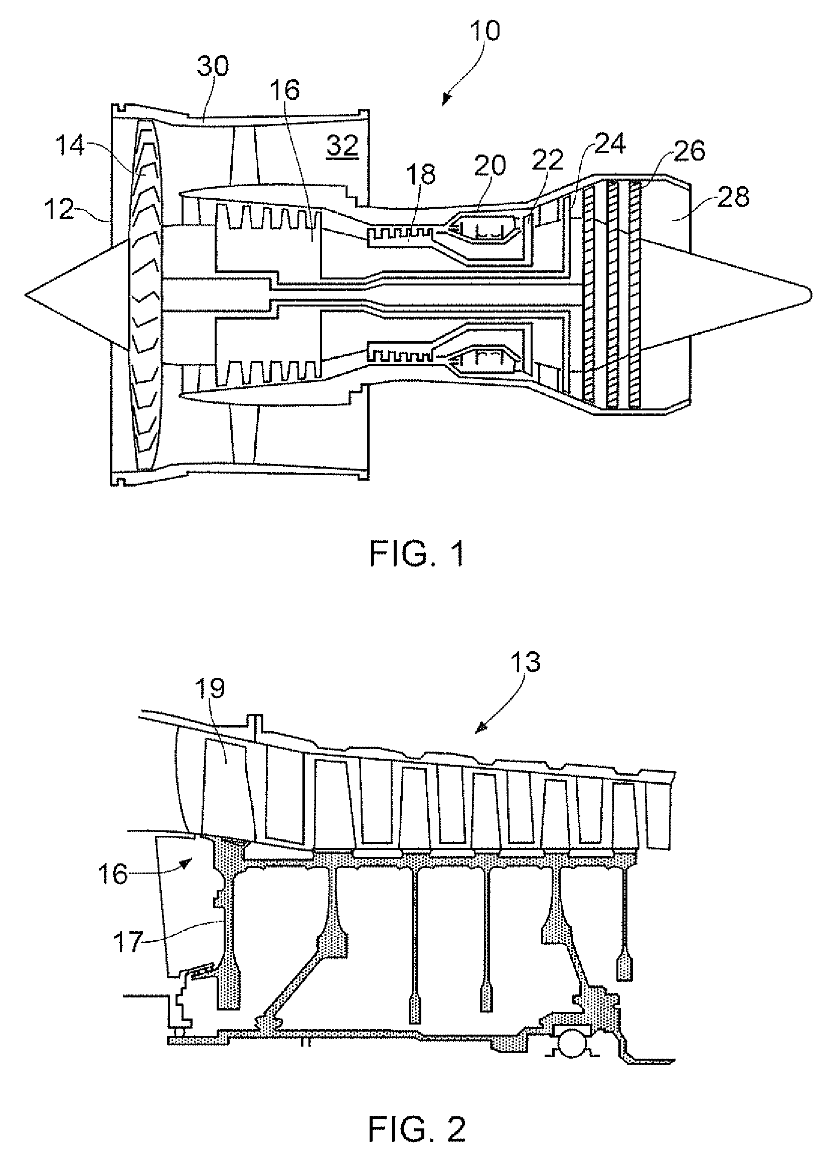
[0040]A gas turbine engine 10 is shown in FIG. 1 and comprises an air intake 12 and a propulsive fan 14 that generates two airflows A and B. The gas turbine engine 10 comprises, in axial flow A, an intermediate pressure compressor 16, a high pressure compressor 18, a combustor 20, a high pressure turbine 22, an intermediate pressure turbine 24, a low pressure turbine 26 and an exhaust nozzle 28. A nacelle 30 surrounds the gas turbine engine 10 and defines, in axial flow B, a bypass duct 32.

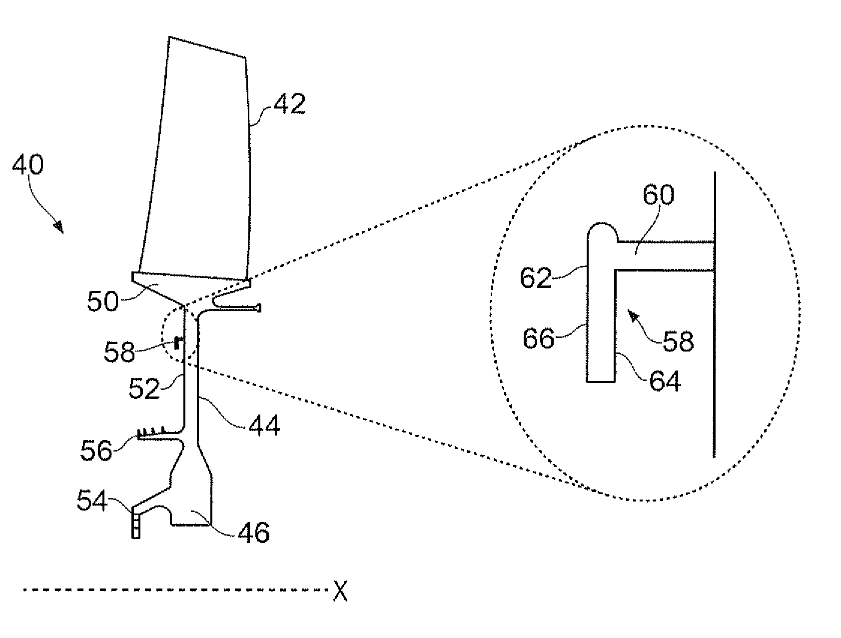
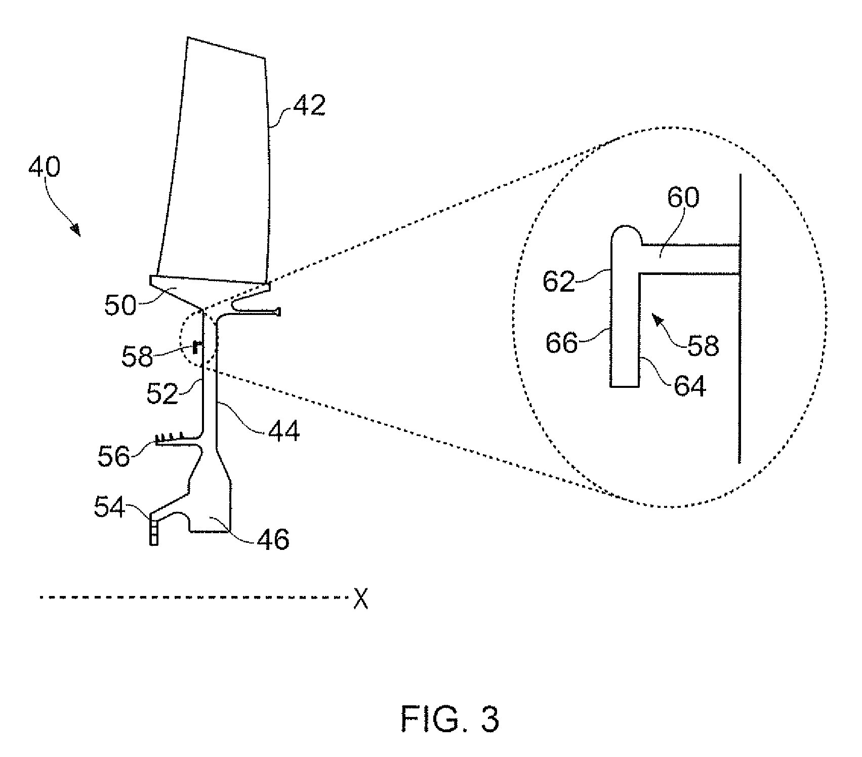
[0041]FIG. 3 shows a rotor 40 of the gas turbine engine 10. In this example, the rotor 40 is an integrally formed intermediate compressor blisk 40, also known as a “bladed disk”. However, the invention is also applicable to rotors in other parts of the engine, such as the high pressure compressor disc 18 and turbine rotors 20, 22, 24, as well as other types of gas turbine rotors such as conventional rotors to which separately formed blades are attached, and rotors for other types of machinery.

[004...


PUM


Abstract

A method of balancing a physical rotor includes: determining a first balance state of the physical rotor at one or more rotational frequencies; identifying one or more balance zones on a surface of the rotor; providing a computerised simulation of the rotor having the first balance state; providing a first test mass in a first test location within one of the balance zones on the rotor simulation; determining a second balance state of the rotor simulation; providing at least one subsequent test mass in at least one subsequent test location within a balance zone on the rotor simulation and determining at least one subsequent balance state of the rotor simulation; selecting a mass and location from one of the first and subsequent test masses and test locations; and performing a material deposition process to add the selected mass of material to the selected location on the physical rotor.

Description

FIELD OF THE INVENTION[0001]The present invention relates to a method of balancing a rotor, particularly but not exclusively, a rotor of a gas turbine engine.BACKGROUND TO THE INVENTION[0002]Rotating components such as gas turbine engine rotors (such as compressor and turbine discs and drums), wheels, crankshafts and drive shafts, which rotate about a centre of rotation, may become unbalanced such that the centre of mass of the rotor does not correspond to the centre of rotation. Once unbalanced, such rotors may then be subject to vibration in use, which is undesirable. An unbalanced rotor may then be balanced using any of several methods.[0003]Conventional gas turbine engines, such as gas turbine engine 10 shown in FIG. 1, comprise a plurality of rotors, including fan 12, compressor rotors 16, 18 and turbine rotors 22, 24, 26. As shown in further detail in FIG. 2, each rotor comprises a disc 17 and a plurality of blades 19 removeably attached at the radially outer rim of the disc 1...

Claims


Application Information

Patent Timeline
Patent Type & Authority Patents(United States)
IPC IPC(8): G01M1/16F04D29/32F04D29/66F01D21/04F01D5/10F01D5/02G01M1/32
CPCG01M1/16F01D5/027F01D5/10F01D21/045F04D29/321F04D29/662G01M1/32Y02T50/671Y02T50/673F01D5/16F01D5/26F01D25/04F01D25/06Y02T50/60
Inventor CLARK, DANIELTUPPEN, STEPHEN JOHN
Owner ROLLS ROYCE PLC
Why Eureka
Try Eureka