Electromechanical generator for converting mechanical vibrational energy into electrical energy

a technology of electrical energy and mechanical vibration, which is applied in the direction of dynamo-electric machines, dynamo-electric components, magnetic circuit shapes/forms/construction, etc., can solve the problem of limiting the range of achievable wall thickness, increasing cost and/or complexity of manufacture, and potentially reducing the level of magnetic flux passing through the coil. , to achieve the effect of reducing the amount of material, and high rigidity

Active Publication Date: 2021-06-08
PERPETUUM +1
View PDF7 Cites 8 Cited by
  • Summary
  • Abstract
  • Description
  • Claims
  • Application Information

AI Technical Summary

Benefits of technology

[0007]The present invention aims at least partially to provide an energy harvester in the form of electromechanical generator which can reliably provide a bobbin which minimizes the amount of material, such as plastic, around the coil used to form the bobbin, so that maximum magnetic flux passes through the coil, yet provides the bobbin with sufficient strength, particularly in the axial direction, to maintain the coil in the desired position when the electromechanical generator is subjected to input mechanical vibration.
[0010]The present invention is predicated on the finding that a conical wall incorporated in the coil mount, the conical wall extending between the coil assembly and the central mast of the electromechanical generator, can provide a highly rigid, thin, axis-symmetric structure capable of supporting axial loads preferentially. The electromechanical generator can therefore incorporate a bobbin which minimizes the amount of material, such as a thermoplastic, around the coil used to form the bobbin, so that maximum magnetic flux passes through the coil. In addition, the bobbin is provided with sufficient strength, particularly in the axial direction, to maintain the coil in the desired position when the electromechanical generator is subjected to input mechanical vibration. The desired technical effects of enhanced magnetic coupling, and minimum mechanical motion of the bobbin and associated coil when subjected to vibration, are achieved, and can be achieved using an injection moulded thermoplastic one-piece bobbin.

Problems solved by technology

The plastic bobbin could be formed by injection moulding, but this process limits the range of achievable wall-thickness.
These options would increase cost and / or complexity of manufacture and would potentially reduce the level of magnetic flux passing through the coil.

Method used


Image

  • Electromechanical generator for converting mechanical vibrational energy into electrical energy
  • Electromechanical generator for converting mechanical vibrational energy into electrical energy
  • Electromechanical generator for converting mechanical vibrational energy into electrical energy

Examples


Embodiment Construction

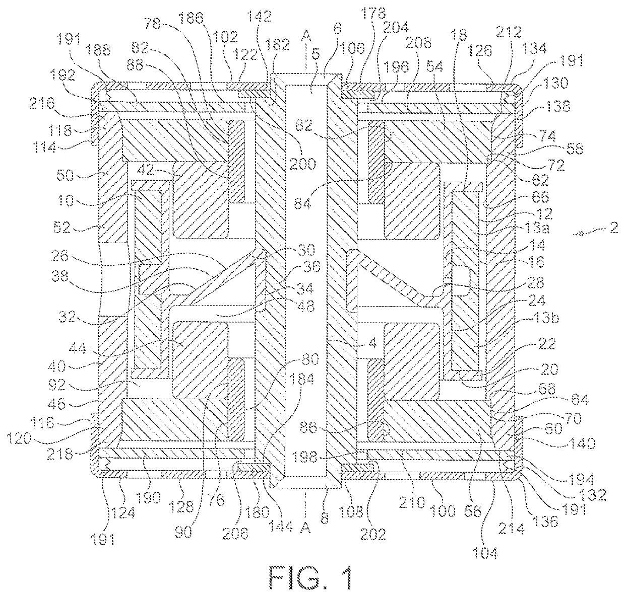
[0016]The electromechanical generator of the present invention is a resonant generator known in the art as “velocity-damped” where substantially all of the work done by the movement of the inertial mass relative to the housing is proportional to the instantaneous velocity of that movement. Inevitably, a portion of that work is absorbed overcoming unwanted mechanical or electrical losses, but the remainder of the work may be used to generate an electrical current via a suitable transduction mechanism, such as the electrical coil / magnetic assembly described below.

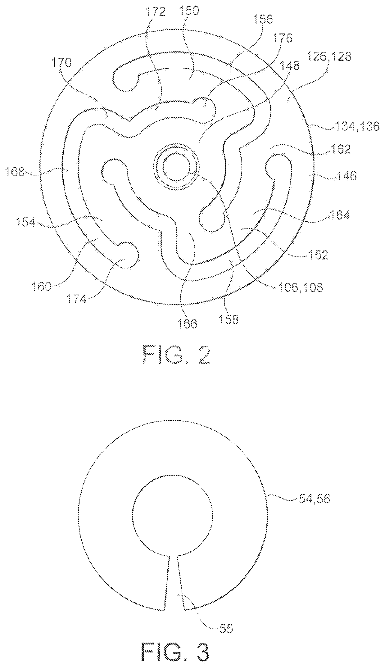
[0017]FIGS. 1 and 2 illustrate an electromechanical generator 2 for converting mechanical vibrational energy into electrical energy in accordance with a first embodiment of the present invention. In operation, the electromechanical generator 2 is enclosed within a housing (not shown) and the device is provided with a fitting (not shown) for securely mounting the electromechanical generator 2 to a support (not shown) from whic...


PUM


Abstract

An electromechanical generator for converting mechanical vibrational energy into electrical energy, the electromechanical generator comprising: a central mast, an electrically conductive coil assembly fixedly mounted to the mast, the coil assembly at least partly surrounding the mast, a mount for the coil assembly extending radially inwardly of the coil assembly and fixing the coil assembly to the mast, wherein the mount comprises a conical wall extending between the coil assembly and the mast, a magnetic core assembly movably mounted to the mast for linear vibrational motion along an axis about an equilibrium position on the axis, the magnetic core assembly at least partly surrounding the coil assembly and the mast, and a biasing device mounted between the mast and the magnetic core assembly to bias the magnetic core assembly in opposed directions along the axis towards the equilibrium position.

Description

CROSS REFERENCE TO RELATED APPLICATION[0001]This application is a US 371 application from PCT / EP2019 / 057200 entitled “An Electromechanical Generator for Converting Mechanical Vibrational Energy into Electrical Energy” filed on Mar. 22, 2019 and published as WO 2019 / 185465 A1 on Oct. 3, 2019, which claims priority to GB Application 1804872.8 filed on Mar. 27, 2018. The technical disclosures of every application and publication listed in this paragraph are hereby incorporated herein by reference.BACKGROUND TO THE INVENTION[0002]The present invention relates to an electromechanical generator for converting mechanical vibrational energy into electrical energy, i.e. a vibration energy harvester. In particular, the present invention relates to such a vibration energy harvester which is a miniature generator capable of converting ambient vibration energy into electrical energy for use, for example, in powering intelligent sensor systems. Such a vibration energy harvester can be used in man...

Claims


Application Information

Patent Timeline
Patent Type & Authority Patents(United States)
IPC IPC(8): H02K35/02H02N2/18H01K1/34H02K1/34
CPCH02K35/02H02N2/186H02K1/34F16F15/03H02K7/1876
Inventor WASENCZUK, ADAM
Owner PERPETUUM
Why Eureka
Try Eureka