Sanitary drain valve

a technology of sanitary drain valve and drain valve body, which is applied in the direction of valve housing, valve operating means/release devices, functional valve types, etc., can solve the problems of time-consuming and expensive removal of actuator and actuator shaft, and achieve the effect of simplifying valve maintenan

Active Publication Date: 2009-08-11
PHARMENTA
View PDF6 Cites 5 Cited by
  • Summary
  • Abstract
  • Description
  • Claims
  • Application Information

AI Technical Summary

Benefits of technology

[0008]It is the object of the present invention to provide a device, which allows for material to be removed from a process while avoiding the deficiencies of the background art. Specifically, it is the object of the present invention to provide a valve for passively draining material from tanks or conduits while minimizing the amount of material held up in the valve after draining is complete. Furthermore, it is the object of the invention to provide an improved drainability of the valve along with easier diaphragm replacement, without the need for disassembly of the valve body or valve body-actuator assembly and, all of the above while allowing for valve installation and maintenance with minimal ground clearance. It is also the object of this invention to provide a design that is flexible and can be fabricated as a 2-part valve body without sacrificing its complete passive drainability. The 2-part design, with a sanitary seal between the two halves positioned above the drain outlet, allows the supply of either part of the valve body early and expeditiously so as not to hold up other equipment fabrication and installation activities even though they might be located at different sites. Furthermore, whereas today's radial diaphragm tank bottom valve body designs are all made as one piece, requiring the valve body to be present for all steps of its fabrication, this invention's 2-part valve body allows the parts to be fabricated, tested, shipped and stocked separately and does not require them to be brought together until time of use. This design approach also allows for the mating of a variety of top halves with a variety of bottom halves, a range of versatility not available today where sanitary valve bodies are fabricated as one-piece units with elements arranged in specific orientations and dedicated for use in specific applications.
[0010]An embodiment of the present invention is also directed to a diaphragm valve where the stationary perimeter (fixed, mounting) seal formed between the diaphragm and the valve body can be formed in one of several ways so designed to minimize hold-up of material draining through the valve body while allowing the diaphragm to be mounted into the valve up through the bottom wall of the valve body and / or allowing the diaphragm to be mounted into the valve from a position above the bottom wall of the valve body. The valve includes a valve body with a seal formed between some portion of the valve body bottom wall with a first process side of the diaphragm which may also include:
[0020]The present invention is also directed to a valve body, wherein replacement of the diaphragm can be performed without disassembly of the valve body into two parts and which would also not require the removal of the actuator from the valve body, thus simplifying valve maintenance and allowing for valve body-actuator installations with minimal clearance between the bottom of the actuator and the floor.

Problems solved by technology

While actuator and actuator shaft removal is both time-consuming and expensive, it also requires that an allowance be made for a substantial amount of space about the installation site of the valve so that the shaft and actuator can be removed.

Method used


Image

  • Sanitary drain valve
  • Sanitary drain valve
  • Sanitary drain valve

Examples


Embodiment Construction

[0037]The present invention will now be described with reference to the accompanying drawings, wherein the same reference numerals will be used to identify the same or similar elements throughout the several views.

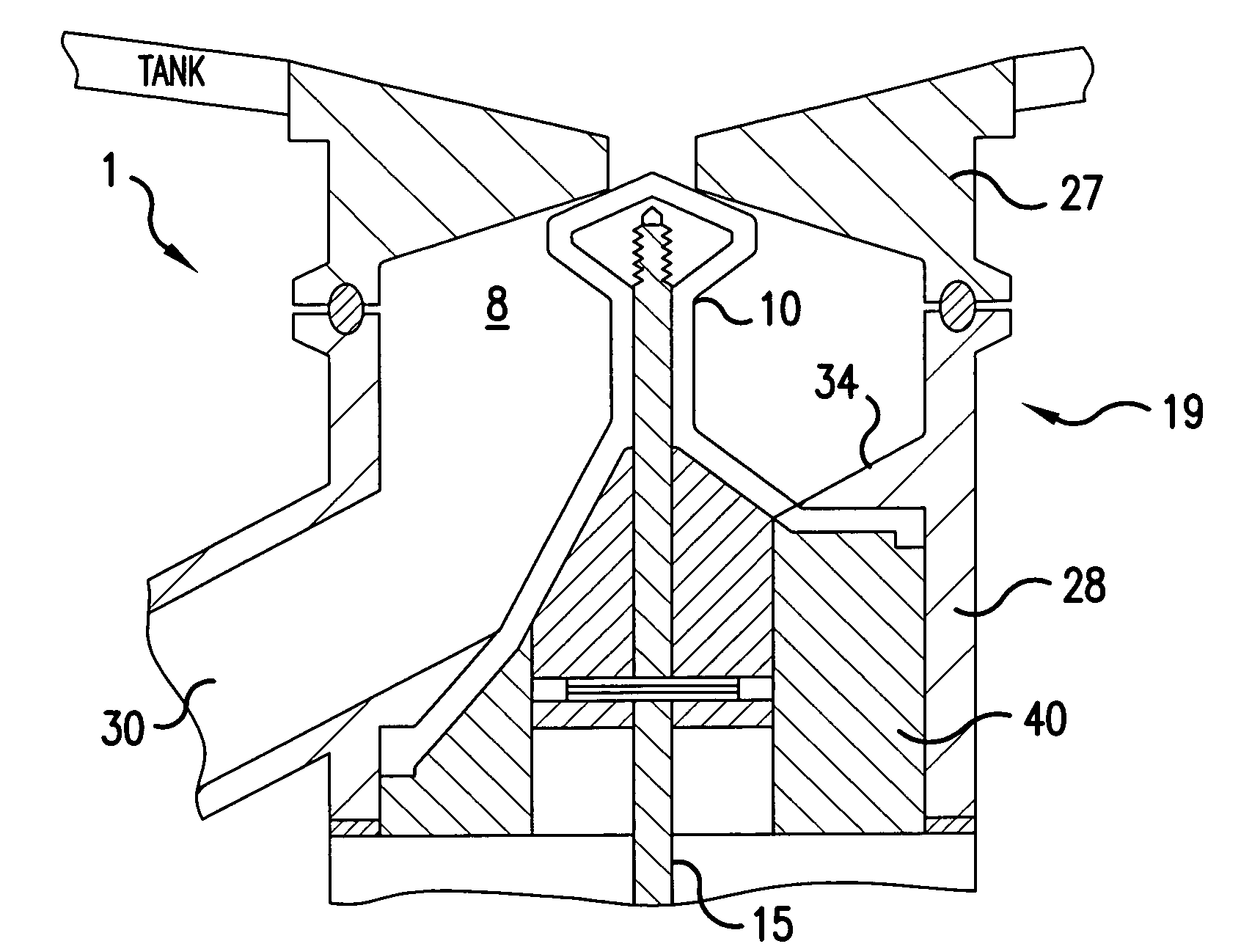
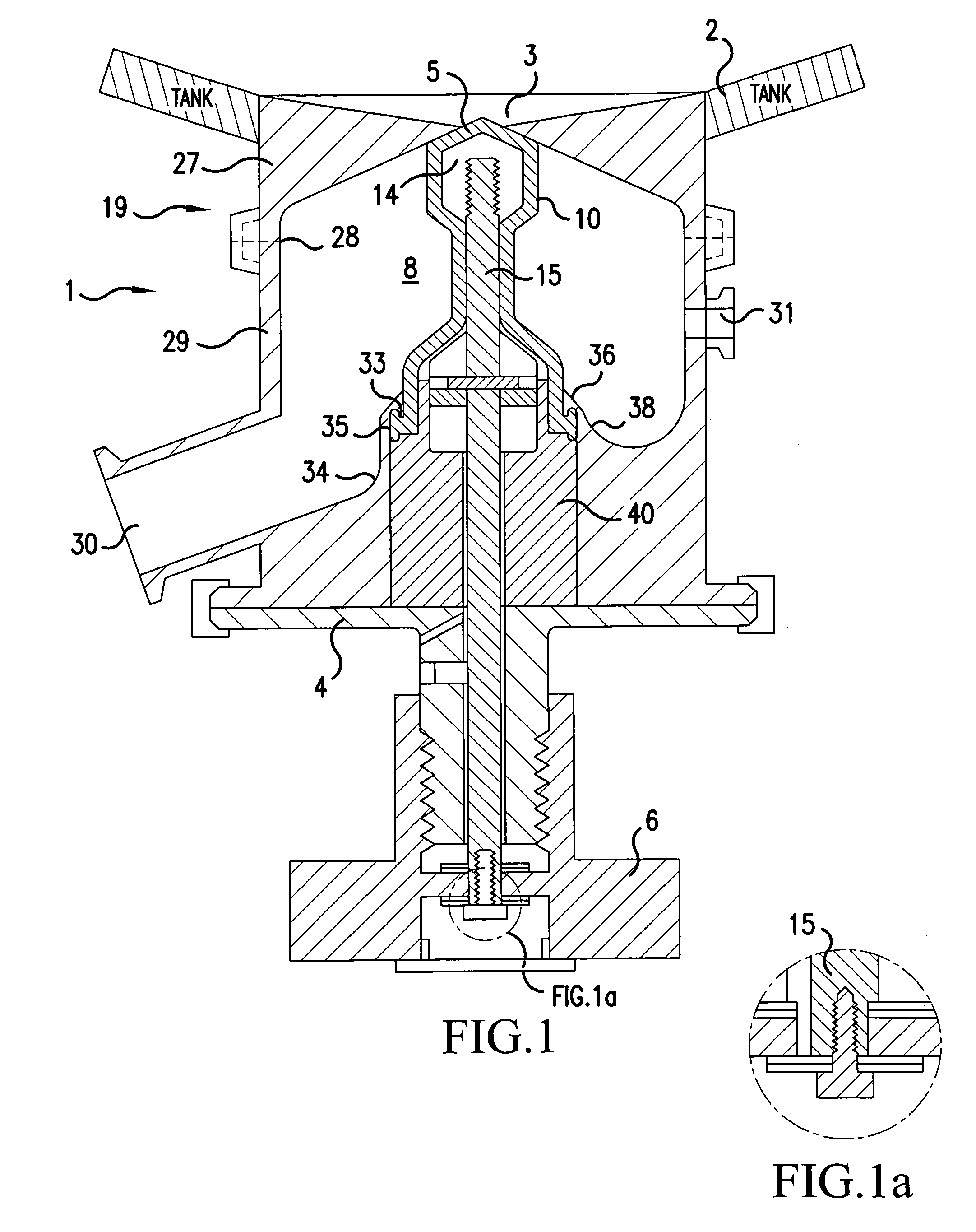
[0038]FIG. 1 illustrates a valve body 19 that may be fabricated in two halves 27, 29 with a joint 28 between the two halves (shown here in dotted lines). The half 27 is mountable to a tank or conduit 2 by welding or other means that would be well known to one having ordinary skill in the art. The half 27 also includes an orifice 3, through which a process within the tank or conduit 2 is sealed by a sealing tip 5.

[0039]The joint 28, if present, is located above the valve body outlet 30 and may also be located above a secondary inlet port 31 to the valve body 19 generally used for the supply of CIP or SIP solutions to the valve body 19. The valve 1 may have an o-ring or packing forming a seal (not shown) between the valve body 19 and the valve actuator shaft 15, isolating th...


PUM


Abstract

A valve assembly includes a valve body having an internal cavity, an orifice in communication with the internal cavity for communicating with a process in a tank or conduit and an outlet through which process material entering the internal cavity through the orifice can be drained from the internal cavity. A valve actuator body includes an actuating shaft having a sealing tip and is mounted for movement in the valve actuator body to seal and unseal the orifice. A diaphragm is mounted to the sealing tip and includes a base that seals with a bottom wall of the valve body. The bottom of the valve body has an aperture that receives the actuating shaft therethrough. The diaphragm is mountable to and removable from the bottom wall of the valve body through the aperture.

Description

CROSS-REFERENCE TO RELATED APPLICATIONS[0001]This nonprovisional application claims priority under 35 U.S.C. § 119(e) on U.S. Provisional Application No. 60 / 638,161, filed on Dec. 23, 2004, the entirety of which is incorporated herein by reference.BACKGROUND OF INVENTION[0002]1. Field of Invention[0003]The present invention relates to the field of withdrawing material from a tank or conduit. In particular, the invention relates to valves for withdrawing material from tanks or conduits where there is a desire for valves that passively drain with a minimum of material hold-up and / or valves where seal change-out can be performed with minimal valve disassembly. (NOTE: While these valves may be designed as “drain” valves, they can be used with equal effectiveness on the side walls of tanks, in process flow lines as well as many other places in the process.) The invention also relates to the desire for equipment to be user-friendly, both at the outset when it is being installed, as well a...

Claims


Application Information

Patent Timeline
Patent Type & Authority Patents(United States)
IPC IPC(8): F16K1/00F16K15/00
CPCF16K27/07F16K41/103F16K31/504
Inventor NEWBERG, DOUGLAS A.
Owner PHARMENTA
Why Eureka
Try Eureka