Anchor Bolt Locator

Active Publication Date: 2013-01-31
SIMPSON STRONG TIE
View PDF2 Cites 7 Cited by
  • Summary
  • Abstract
  • Description
  • Claims
  • Application Information

AI Technical Summary

Benefits of technology

The present invention provides an economical and easy-to-use anchor bolt locator. The chair of the locator is made of sheet metal and can permanently attach a structural nut without welding, which improves the structural integrity of the nut. The locator is designed to receive a piece of threaded rod in the nut. The connection between the threaded rod and the locator is secure, as a central opening in the locator allows for precise positioning, and tongues stop the rod from being inserted too far into the nut. This prevents the anchor from being inserted too far into the nut, which can lead to degradation of the anchor and less protrusion for attaching other devices.

Problems solved by technology

Welding can crack nuts, especially if they are heat treated.
If the anchor is threaded too far into the nut, the bottom of the anchor may be placed too close to the bottom of the concrete form which can lead to degradation of the anchor, and it will also mean that less of the anchor protrudes from the top of the form for attaching other devices.

Method used


Image

  • Anchor Bolt Locator
  • Anchor Bolt Locator
  • Anchor Bolt Locator

Examples


Embodiment Construction

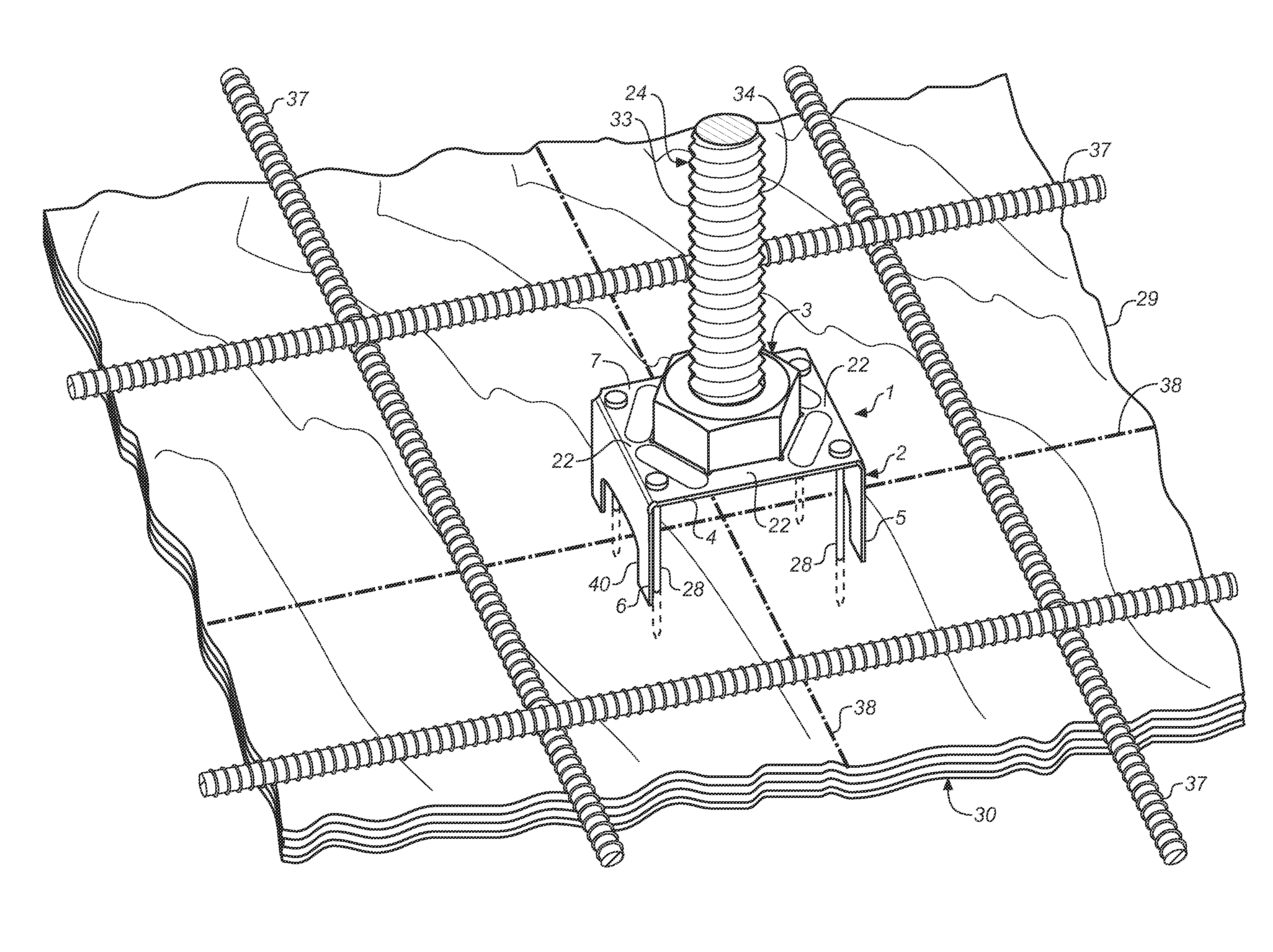
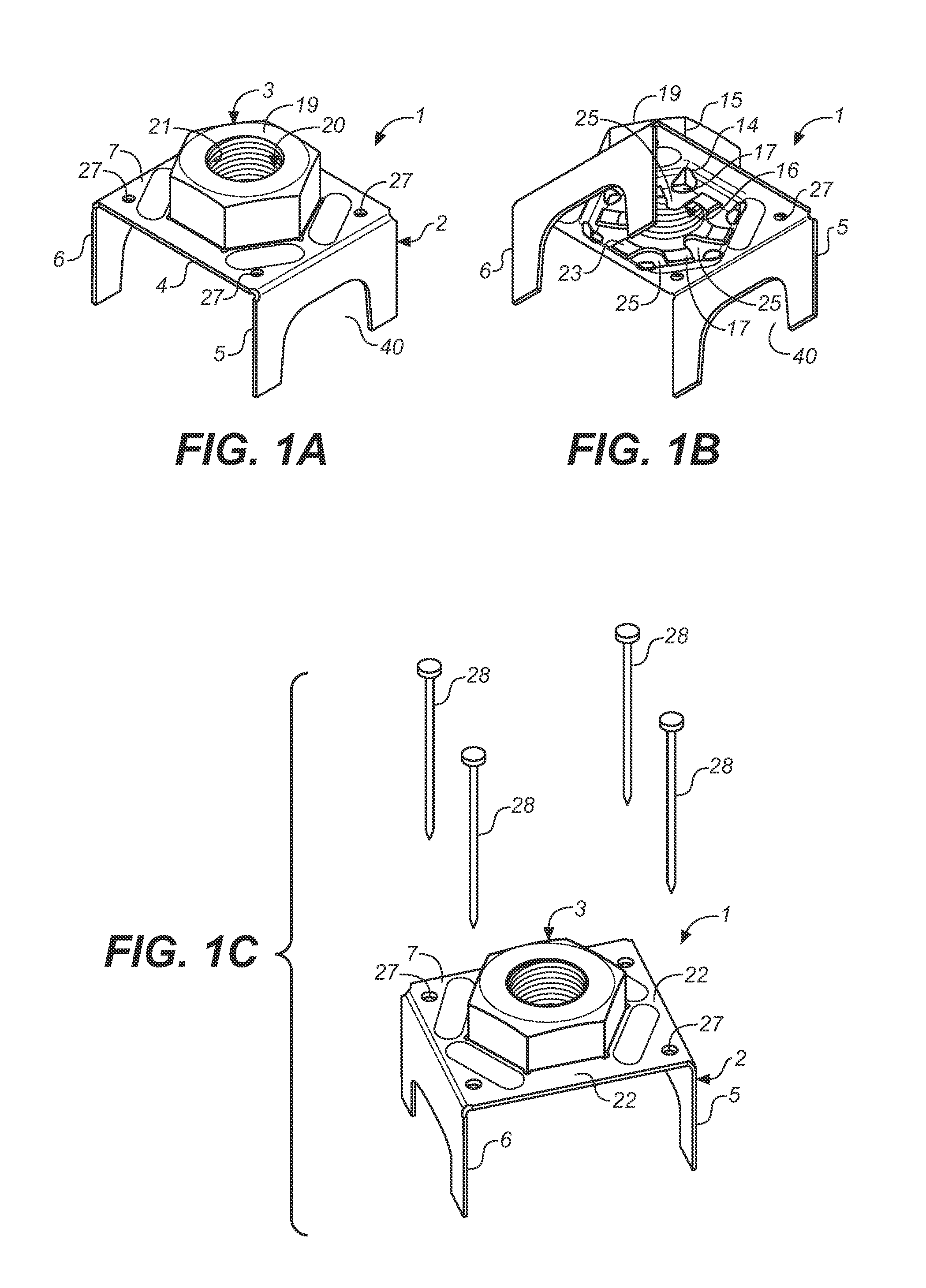
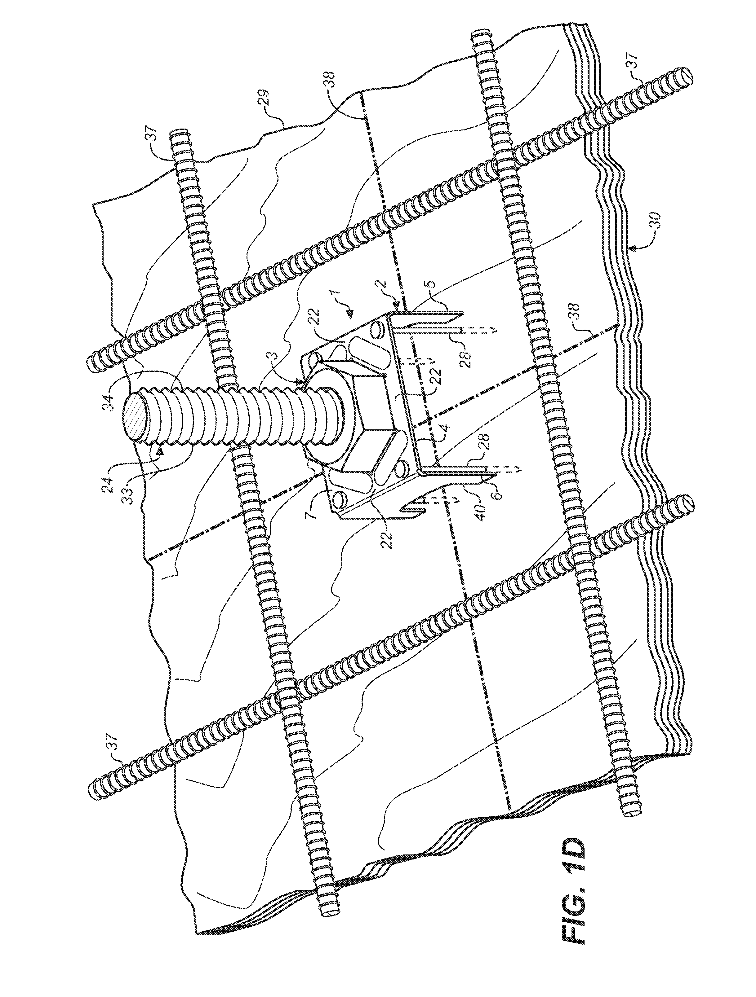
[0039]FIG. 1A, shows the preferred, non-welded anchor bolt locator 1 of the present invention made from a galvanized sheet metal chair 2 and a structural nut 3 attached to the chair 2 by way of a friction fit.

[0040]As shown in FIG. 1A, preferably the chair 2 of the anchor bolt locator 1 is a u-shaped body having a bridge 4 that connects two legs 5 and 6. Preferably, the bridge 4 is substantially rectangular with pairs of opposed sides and the legs 5 and 6 of the chair 2 are connected to the bridge 4 at one pair of opposed sides. Preferably, the legs 5 and 6 of the chair 2 depend from the bridge 4 at right angles to the bridge 4. Preferably, the plurality of legs 5 and 6 extend away from the top surface 7 of the of the bridge 4.

[0041]As shown in FIGS. 1E and 2D-2F, the bridge 4 is formed with a depression 8 that receives the structural nut 3. The structural nut 3 is connected to the bridge 4 by frictional engagement and is held securely in place. The inner surface 9 of the side wall ...


PUM

PropertyMeasurementUnit
Thicknessaaaaaaaaaa

Abstract

An anchor bolt locator is provided that is inexpensively manufactured on automatic die-press machines from sheet steel and a structural nut that does not require any welding, while also being easy to use and install with current, commonly-used building practices and anchor designs. The anchor bolt locator is made from a galvanized sheet metal chair and a structural nut attached to the chair by way of a friction fit.

Description

BACKGROUND OF THE INVENTION[0001]The present invention relates to a concrete embedded insert, called an anchor bolt locator, for properly locating and supporting a bolt or anchoring member during the pouring and curing of a concrete member, such that bolt will be properly placed in the cured concrete.[0002]A concrete slab member is a common structural element of modern buildings. Horizontal slabs of steel-reinforced concrete are used to construct slab foundations, floors, ceilings, decks and exterior paving.[0003]Concrete slabs are built using formwork—a type of boxing into which the wet concrete is poured. Typically, if the slab is to be reinforced, steel reinforcing rods are used, and these are positioned within the formwork before the concrete is poured. This steel reinforcing is often called rebar. Plastic tipped metal, or plastic bar chairs are typically used to hold the reinforcing rods away from the bottom and sides faces of the formwork, so that when the concrete sets it com...

Claims


Application Information

Patent Timeline
IPC IPC(8): E04B1/41B23P17/00
CPCY10T29/49826E04B1/4157E04G21/185Y10T29/49908E04B1/4128
Inventor LIN, JIN-JIEELLIS, TIMOTHY S.
Owner SIMPSON STRONG TIE
Why Eureka
Try Eureka