Fluid dispenser

Active Publication Date: 2013-01-31
APTAR FRANCE SAS
View PDF9 Cites 11 Cited by
  • Summary
  • Abstract
  • Description
  • Claims
  • Application Information

AI Technical Summary

Benefits of technology

[0006]Consequently, an object of the present invention is to remedy the above-mentioned drawbacks of the prior art by defining a novel type of dispenser that is particularly suitable, and to do so by replacing a conventional dispenser/pipette. The first object of the present invention is to avoid any loss of fluid from the cannula. Another object of the present invention is to dis

Problems solved by technology

However, a drawback exists with this type of dispenser/pipette associated with the fact that the cannula is dipped into the fluid stored in the reservoir.
The partial or complete drop may be lost in handling the cannula, or may even increase the volume of the drop that is

Method used


Image

  • Fluid dispenser
  • Fluid dispenser

Examples


Example

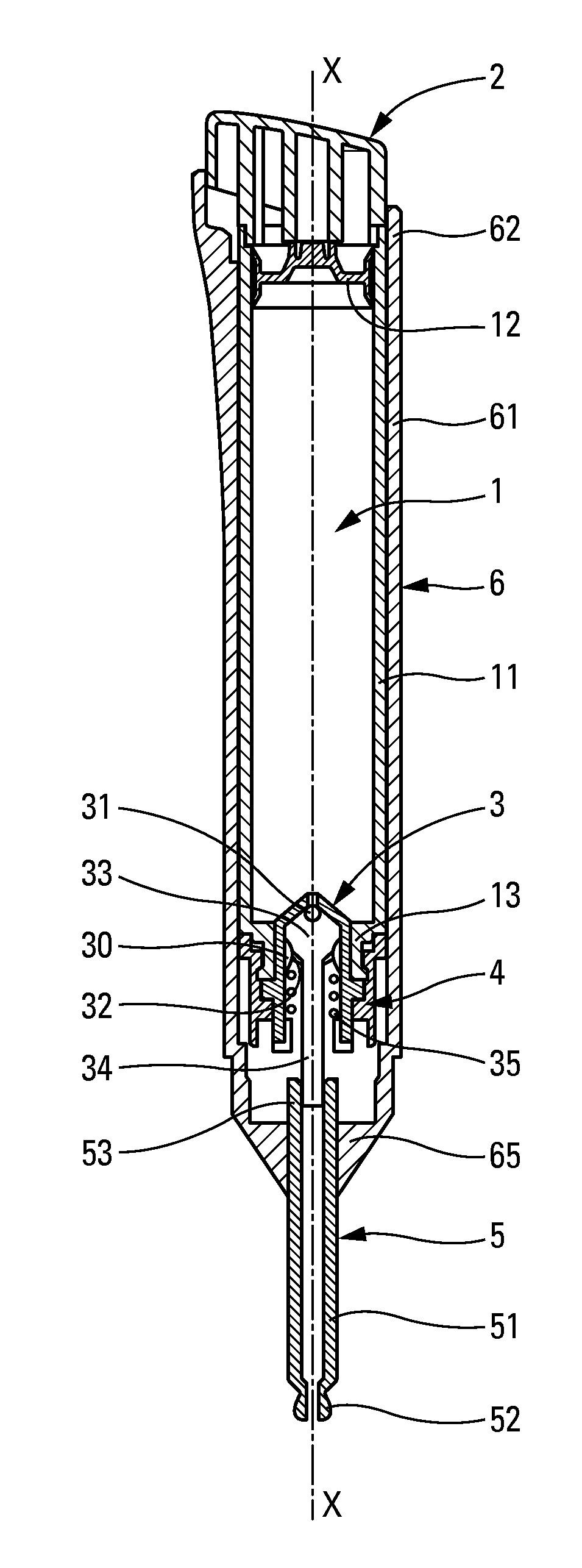
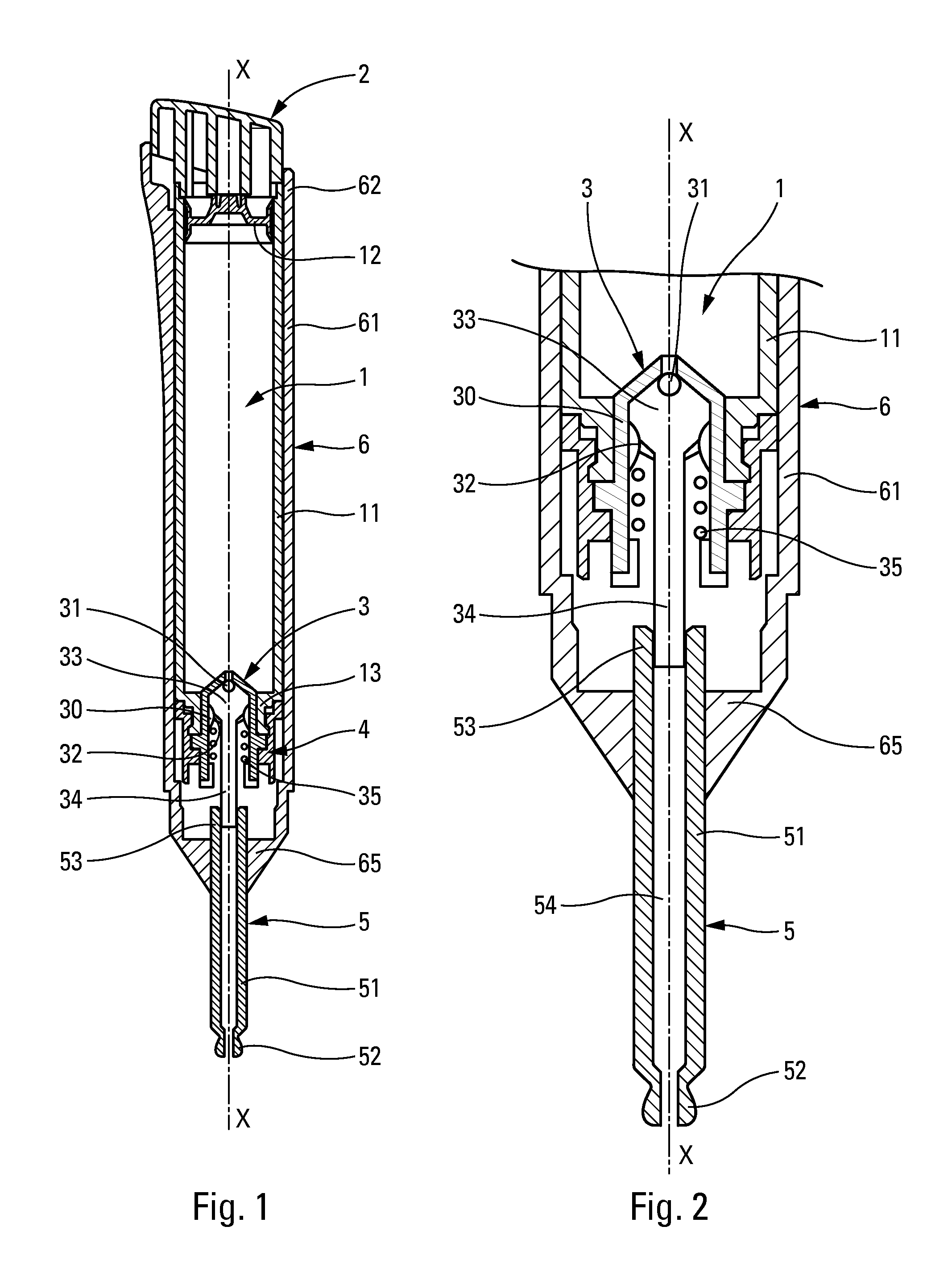
[0019]The dispenser shown in the figures comprises six component elements, namely: a reservoir 1; a pusher 2; a pump 3; a fastener ring 4; a dispenser cannula 5; and a casing 6. All of the component elements are disposed on a longitudinal axis X: some component elements may be circularly symmetrical around the axis X.

[0020]The fluid reservoir 1 includes a cylindrical slide cylinder 11 inside which a follower piston 12 is slidably mounted. When the reservoir is full, the piston 12 is situated at one end of the cylinder 11, remote from the other end that forms a neck 13. A volume is thus constituted of capacity that varies as the follower piston 12 is moved inside the slide cylinder 11. With this type of reservoir, the fluid contained in the reservoir is always protected from the outside air, and thus cannot deteriorate.

[0021]The pusher 2 is disposed at the end of the slide cylinder 11 that is remote from the neck 13, i.e. just above the follower piston 12, when the reservoir is full ...


PUM


Abstract

A fluid dispenser comprising:
    • a fluid reservoir (1); and
    • a pump (3) comprising a pump body (30) and an actuator rod (34), defining between them a pump chamber (33) having a predetermined maximum volume, the rod (34) being axially movable in the body (30) so as to vary the volume of the pump chamber (33);
    • the dispenser being characterized in that it further comprises a dispenser cannula (5) that is mounted on the actuator rod (34) and that includes a dispenser outlet (52) that is suitable for forming a drop of fluid that separates from the cannula (5) by gravity, the determined maximum volume of the pump chamber (33) being substantially equal to the volume of the drop of fluid that is dispensed at the dispenser outlet (52).

Description

CROSS REFERENCE TO RELATED APPLICATION[0001]This application claims the benefit under 35 U.S.C. §119(e) of pending U.S. provisional patent application Ser. No. 61 / 544,820, filed Oct. 7, 2011, and priority under 35 U.S.C. §119(a)-(d) of French patent application No. 11 56778, filed Jul. 25, 2011.TECHNICAL FIELD[0002]The present invention relates to a fluid dispenser comprising a fluid reservoir and a conventional manual pump that defines a variable-volume pump chamber between a pump body and an actuator rod. The purpose of moving the actuator rod is to vary the volume of the pump chamber that, in the rest position, defines a predetermined maximum volume. This type of dispenser is very frequently used in the fields of perfumery, cosmetics, or even pharmacy for dispensing fluids of diverse viscosities.BACKGROUND OF THE INVENTION[0003]In the prior art, dispensers also exist in the form of pipettes comprising a dispenser cannula that forms a dispenser outlet that is suitable for forming ...

Claims


Application Information

Patent Timeline
IPC IPC(8): G01F11/00B65D88/54
CPCB01L3/0265G01F11/027B05B11/0048B05B11/0059B05B11/3015B05B11/3074B01L3/0272B01L2300/0838B01L2400/0457B01L2400/0478B01L2400/0616B05B11/0035B05B11/3004B05B11/309B05B11/3094B05B11/0037B05B11/1004B05B11/1015B05B11/028B05B11/109B05B11/1074B05B11/1094B05B11/0038
Inventor DUQUET, FREDERICMARTINS-REIS, SANDRAMOREAU, FRANCIS
Owner APTAR FRANCE SAS
Why Eureka
Try Eureka