Apparatus and method

a technology of pipes and apparatus, applied in the field of pipes, can solve the problems of substantial access problems and cost implications, prone to failure, and the upgrading and replacement of ageing utilities pipeline infrastructures

Active Publication Date: 2017-10-26
SYNTHOTECH
View PDF1 Cites 0 Cited by
  • Summary
  • Abstract
  • Description
  • Claims
  • Application Information

AI Technical Summary

Benefits of technology

[0066]In some embodiments, in which the installation location is the aforementioned installation pad or platform, means may be provided for preventing the insertion device lifting (i.e. advancing in an insertion direction) the installation pad or platform except for when a next connection fitting to be installed has already been appropriately placed thereon by the conveyance device. Such means may for example be constituted by, or comprise, a respective nose or extension portion of each of the above-mentioned loading members, which respective nose or extension portions are configured so as to engage or overlie a portion of the installation pad or platform so as prevent lifting movement thereof when the respective loading member is in at least its maximum advanced (forward) position, relative to the storage device.
[0067]In some of the above embodiments of the invention there may additionally be provided, for example as part of the storage device or as an independent component of the installation means itself, moveable cover means for selectively retaining, e.g. by covering one or more portions of, a connection fitting located on the installation pad o...

Problems solved by technology

Maintenance, upgrading and replacement of ageing utilities pipeline infrastructures are major issues facing utilities companies such as water and gas utilities companies.
Utilities supply pipelines and the connections between main and consumer service connection pipelines are typically located underground, presenting substantial access problems and cost implications when maintenance, upgrading or replacement is required.
Ageing pipelines, of both main and consumer connection types, are also vulnerable to failure and leakage of fluid from pipelines is a known hazard, which can be particularly serious in the case of gas...

Method used


Image

  • Apparatus and method
  • Apparatus and method
  • Apparatus and method

Examples


Embodiment Construction

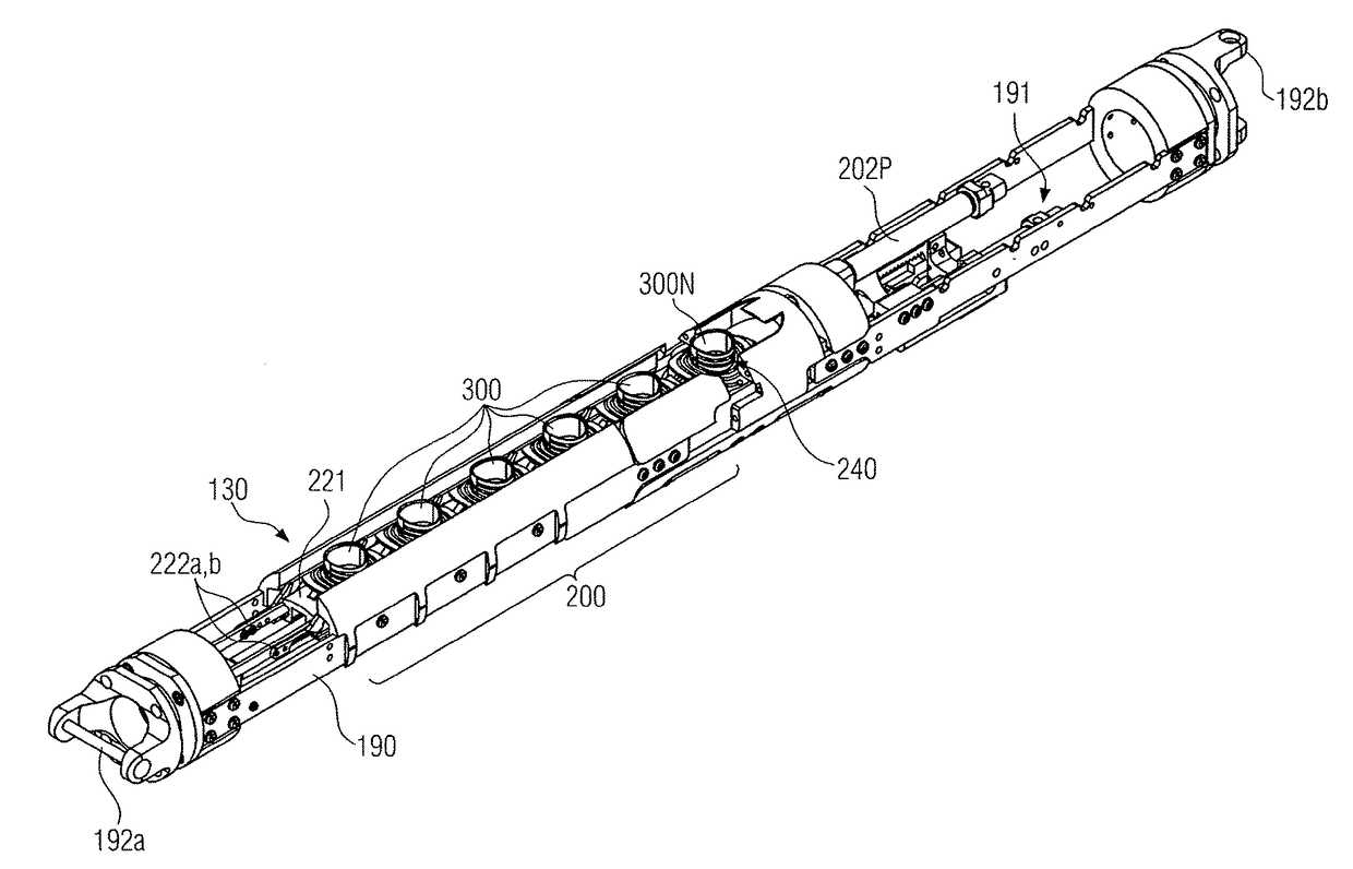
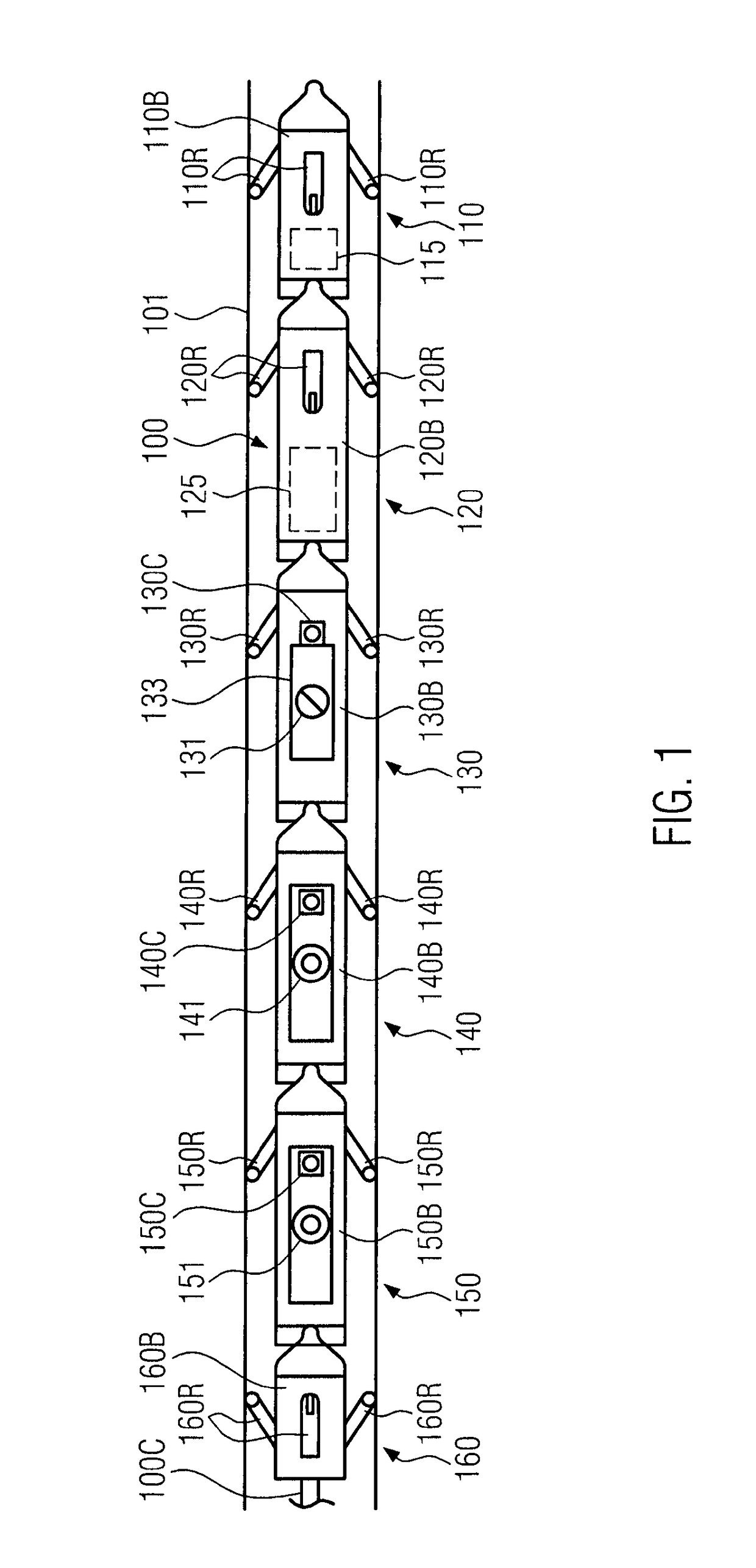
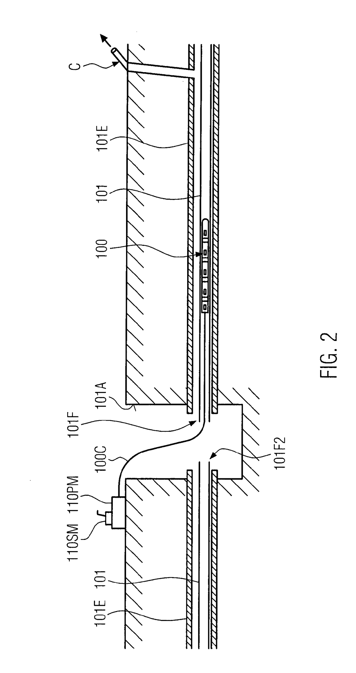
[0121]FIG. 1 is a plan view schematic illustration of a pipeline robot 100 located within a newly installed utilities main pipeline 101. An enlarged scale view of a typical operational environment of the robot 100 is shown in FIG. 2. It can be seen from FIG. 2 that, in the scenario illustrated, the robot 100 has been introduced into a newly installed main pipeline 101 via an underground inspection well 101A. The newly installed utilities main pipeline 101 is itself located within a pre-existing main pipeline 101E of larger diameter. It is to be understood that the free end 101F of the main pipeline 101 that is exposed to the well 101A may be coupled to the free end 101F2 of a second length of newly installed main pipeline 101 that also terminates in the well 101A once consumer service connection (or other types of side or branch connection) pipelines have been connected to the main pipeline 101.

[0122]At some point along the main pipeline 101 there is located a junction between the m...


PUM


Abstract

An apparatus for installing a connection fitting into an aperture formed in a wall of a main pipeline in the making of a service connection between a side connection and the main pipeline includes propulsion means for propelling the apparatus along the main pipeline to a site at which the service connection is to be made, and installation means for installing, from within the main pipeline, at least a portion of the connection fitting into the aperture. The installation means may include a storage device for storing at least one connection fitting intended for installation, a conveyance device for conveying a connection fitting to be installed from the storage device to an installation location, and an insertion device for inserting the connection fitting conveyed to the installation pad or platform from the installation pad or platform into the aperture formed in the wall of the main pipeline.

Description

TECHNICAL FIELD[0001]This invention relates to pipelines, especially but not exclusively to apparatus for use in the maintenance or installation of pipelines. More particularly, though not exclusively, the invention relates to apparatus for use in the making of a service connection to a pipeline.BACKGROUND OF THE INVENTION[0002]Maintenance, upgrading and replacement of ageing utilities pipeline infrastructures are major issues facing utilities companies such as water and gas utilities companies. Pipeline networks typically include main supply pipelines (also referred to as the “mains” supply) and consumer service connection pipelines. (A “pipeline” or “pipe” may alternatively be termed simply a “conduit”, and as used herein such terms may be used interchangeably.) The consumer service connection pipelines are connected to the main supply pipelines typically by means of a T-connection, to deliver a supply of fluid such as water or gas to a consumer's premises from the main supply pip...

Claims


Application Information

Patent Timeline
IPC IPC(8): F16L55/26F16L41/08
CPCF16L41/082F16L55/265
Inventor LANGDALE, SIMON JOHNLITTLE, WESLEY JAMES
Owner SYNTHOTECH
Why Eureka
Try Eureka