Gas spring with dynamically controllable damping

a technology of dynamic control and gas spring, applied in the direction of spring/damper design characteristics, vibration dampers, mechanical instruments, etc., can solve the problem that linear reciprocating machines are typically subject to the effect of damping

Inactive Publication Date: 2013-01-31
MILINKOVIC MIRO
View PDF8 Cites 9 Cited by
  • Summary
  • Abstract
  • Description
  • Claims
  • Application Information

AI Technical Summary

Problems solved by technology

Linear reciprocating machines are typically subject to two problems.

Method used


Image

  • Gas spring with dynamically controllable damping
  • Gas spring with dynamically controllable damping
  • Gas spring with dynamically controllable damping

Examples


Embodiment Construction

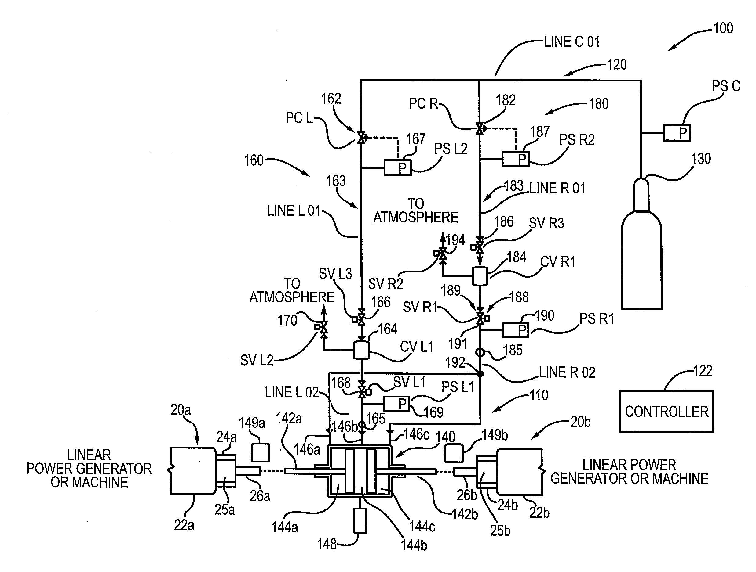
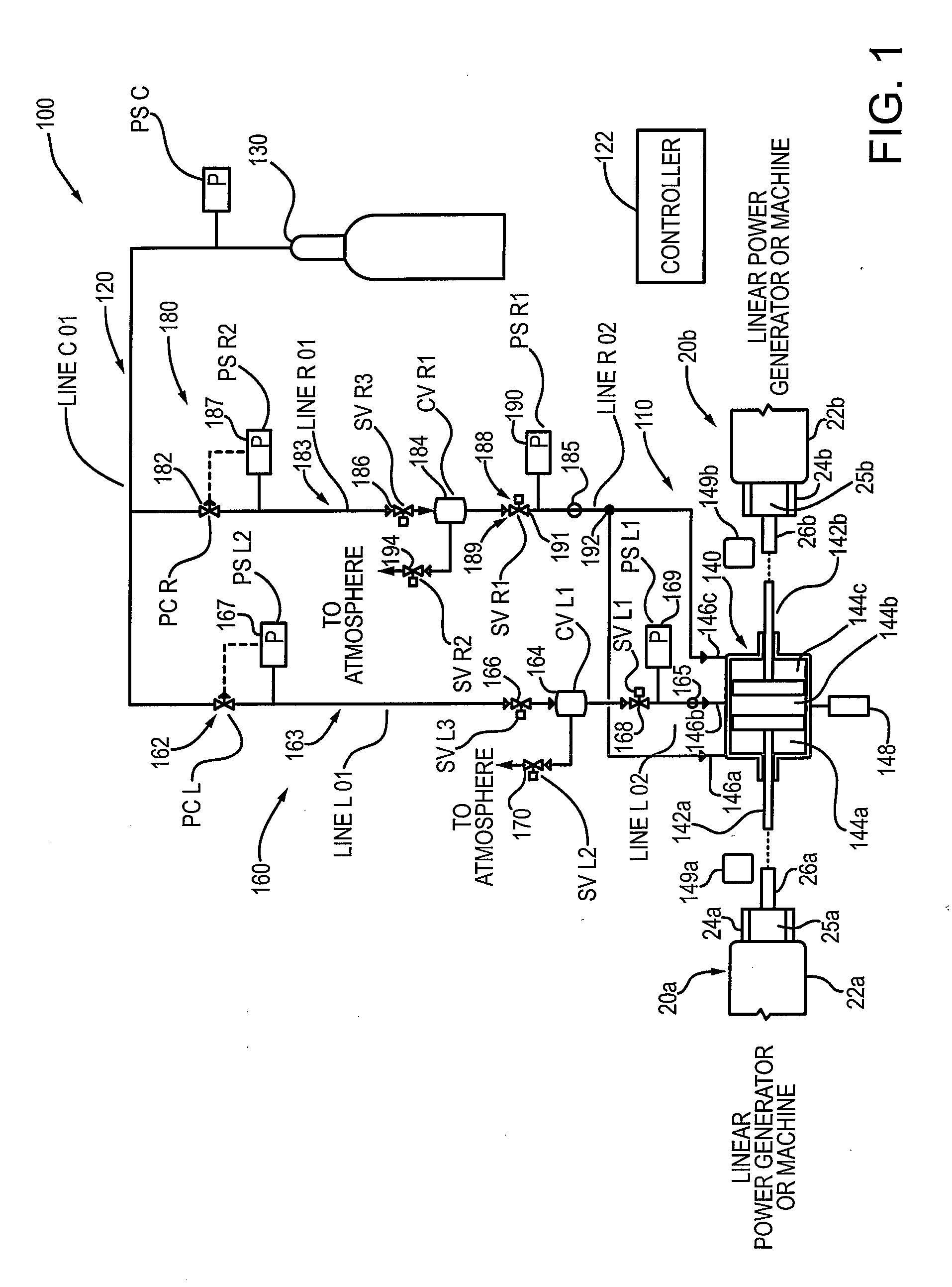
[0015]Reference is first made to FIG. 1, which shows a gas spring system according to an embodiment of the invention. The gas spring system is indicated generally by reference 100 and according to an exemplary embodiment is configured to operate with a linear reciprocating machine or a linear power generator. While the gas spring 100 according to embodiments of the present invention is described in the context of a linear reciprocating machine, or a linear power generator, it will be appreciated that the gas spring is suitable for other applications requiring a spring or damping force that can according to an aspect of the invention be dynamically controlled as also described in more detail below.

[0016]As shown in FIG. 1, the gas spring system 100 generally comprises a gas spring assembly 110, a pressure control network 120, a controller 122 and a gas supply system 130.

[0017]In the context of the present exemplary implementation, the gas spring system is configured to work with a pa...


PUM


Abstract

A gas spring suitable for controlling motion of a linear power generator or a linear machine. According to an embodiment, the gas spring comprises a cylinder and a pressure control network. The cylinder comprises two pistons in a coaxial arrangement and three controllable gas volumes or chambers. Each of the pistons includes a piston rod or shaft that is configured to couple to respective drive shaft(s) on the linear power generator. The pressure control network is operatively coupled to each of the three gas volumes and configured with a controller to control the gas pressure in the gas volumes to vary the resistance of the pistons to the movement of the respective drive shaft(s) on the linear power generator. According to another embodiment, the cylinder comprises one piston and two controllable gas volumes or chambers operatively coupled to the pressure control network.

Description

FIELD OF THE INVENTION[0001]The present invention relates to a gas spring, and more particularly, to a gas spring configured for dynamically controlling the stiffness and / or rebound, and is suitable for use with a linear movement machine or generator.BACKGROUND OF THE INVENTION[0002]Linear reciprocating machines are typically subject to two problems. The first concerns efficient energy storage and release during the acceleration and de-acceleration cycles. The second concern is the prevention or reduction of mechanical vibrations. Mechanical vibrations can reduce efficiencies and are typically directed or transmitted to the base of the machine.[0003]Accordingly, there remains a need for improvements in the art.BRIEF SUMMARY OF THE INVENTION[0004]The present invention comprises embodiments of a gas spring and / or a gas spring configured with a mechanism for controlling the dampening force, i.e. stiffness, and / or rebounding force of the gas spring.[0005]According to an embodiment, the ...

Claims


Application Information

Patent Timeline
Patent Type & Authority Applications(United States)
IPC IPC(8): F16F9/02F16F9/19
CPCF16F2230/18F16F9/0218
Inventor MILINKOVIC, MIRO
Owner MILINKOVIC MIRO
Why Eureka
Try Eureka