Circuit for compensating color shift of a color sequential display method and method thereof

a color shift and circuit technology, applied in the field of compensating circuits, can solve the problems of uneven color levels on display panels, low red sub-pixel illumination, and insufficient instantaneous output power

Inactive Publication Date: 2013-01-31
CHUNGHWA PICTURE TUBES LTD
View PDF1 Cites 10 Cited by
  • Summary
  • Abstract
  • Description
  • Claims
  • Application Information

AI Technical Summary

Benefits of technology

[0011]The present invention provides a circuit for compensating a color shift of the color sequential display method and method thereof. The circuit and method thereof adjust gray levels of a pixel according to color saturation of the pixel, and maximum luminances of red light, green light, blue light, and white light of a display panel. Therefore, the present invention can solve a problem of uneven color levels of the display panel due to insufficient response time of liquid crystals of the display panel.

Problems solved by technology

However, due to insufficient response time of the liquid crystal LCR, the liquid crystal LCR is not turned on completely when the backlight BLR is turned on, resulting in the luminance of the red sub-pixel being lower than 100% (such as 70%).
Thus, the display panel may exhibit uneven color levels.
However, because the turning-on times of the backlights BLR, BLG, and BLB are shorter (the duty cycles of the backlights BLR, BLG, and BLB are 25%), the instantaneous luminances of the red, green, and blue sub-pixels must be increased to meet luminance requirements of the display panel, resulting in instantaneous output power being too high.
Therefore, the above mentioned prior arts for solving the problem of the uneven color levels of the display panel are not good choices for a designer of the display panel.

Method used


Image

  • Circuit for compensating color shift of a color sequential display method and method thereof
  • Circuit for compensating color shift of a color sequential display method and method thereof
  • Circuit for compensating color shift of a color sequential display method and method thereof

Examples


Embodiment Construction

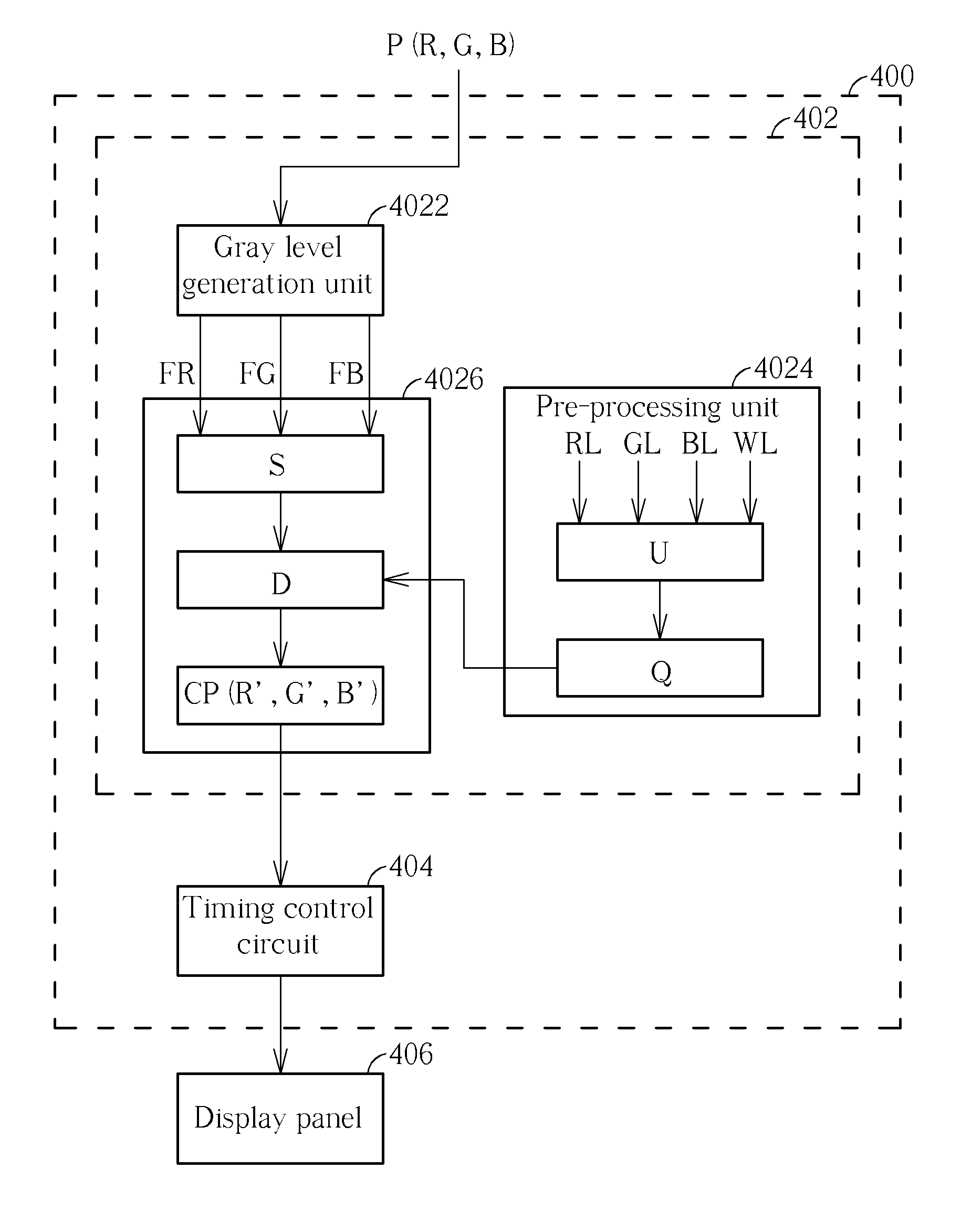
[0026]Please refer to FIG. 4. FIG. 4 is a diagram illustrating a circuit 400 for compensating color shift that occurs when performing a color sequential display method according to an embodiment. The circuit 400 includes an image processing unit 402 and a timing control circuit 404, where the image processing unit 402 includes a gray level generation unit 4022, a pre-processing unit 4024, and a color compensation unit 4026. The color compensation unit 4026 is coupled to the pre-processing unit 4024 and the gray level generation unit 4022. The image processing unit 402 is used for compensating gray levels of red, green, and blue sub-pixels R, G, and B of a pixel P to generate gray levels of red, green, and blue sub-pixels R′, G′, and B′ of a compensated pixel CP. The timing control circuit 404 is coupled to the image processing unit 402 for sequencing the gray levels R′, G′, and B′ of the red, green, and blue sub-pixels of the compensated pixel CP according to a color sequential disp...


PUM


Abstract

A circuit for compensating color shift of a color sequential display method includes an image processing unit and a timing control circuit. The image processing unit includes a gray level generation unit, a pre-processing unit, and a color compensation unit. The gray level generation generates first gray levels of red, green, and blue sub-pixels. The pre-processing unit generates a pure color uniformity of a display panel and a color compensation value. The color compensation unit generates a color saturation of a pixel, a compensation difference of the pixel, and gray levels of red, green, and blue sub-pixels of a compensated pixel. The timing control circuit sequences the gray levels of the red, green, and blue sub-pixels of the compensated pixel according to the color sequential display method, and outputs the gray levels of the red, green, and blue sub-pixels of the compensated pixel to the display panel.

Description

BACKGROUND OF THE INVENTION[0001]1. Field of the Invention[0002]The present invention is related to a compensation circuit and method thereof, and particularly to a compensation circuit and method thereof that can compensate color shift that occurs when performing a color sequential display method.[0003]2. Description of the Prior Art[0004]Utilizing a color sequential display method to display red, green, and blue light of a display panel eliminates the need for color filters to display the red, green, and blue light of the display panel. A color mix theory of the color sequential display method forms predetermined colors by rapidly switching backlight corresponding to the red, green, and blue light, so that red, green, and blue light sub-pixels are shown during a frame interval. Please refer to FIG. 1A, FIG. 1B, FIG. 1C, and FIG. 1D. FIG. 1A, FIG. 1B, FIG. 1C, and FIG. 1D are diagrams illustrating a pixel of a frame displaying red, green, blue, and white light, respectively. As sho...

Claims


Application Information

Patent Timeline
Patent Type & Authority Applications(United States)
IPC IPC(8): G09G5/02
CPCG09G5/02G09G3/3607G09G2310/08G09G2320/041G09G2320/0276G09G2310/0235G09G2320/0242
Inventor TSAI, CHI-CHUNGTAI, WEN-CHIH
Owner CHUNGHWA PICTURE TUBES LTD
Why Eureka
Try Eureka