Eureka AIR delivers breakthrough ideas for toughest innovation challenges, trusted by R&D personnel around the world.

Power line communcation method and power line communication system

a communication system and power line technology, applied in the field of communication methods and systems, can solve problems such as bringing a lot of inconvenience to users, and achieve the effect of enhancing the convenience of a data collector, and not wasting a lot of time and manpower

Inactive Publication Date: 2013-08-08
DELTA ELECTRONICS INC
View PDF13 Cites 5 Cited by
  • Summary
  • Abstract
  • Description
  • Claims
  • Application Information

AI Technical Summary

Benefits of technology

This patent is about a method and system for improving communication between a data collector and a micro inverter in a power line communication (PLC) system. The main goal is to save time and reduce effort while ensuring the two devices can easily identify each other.

Problems solved by technology

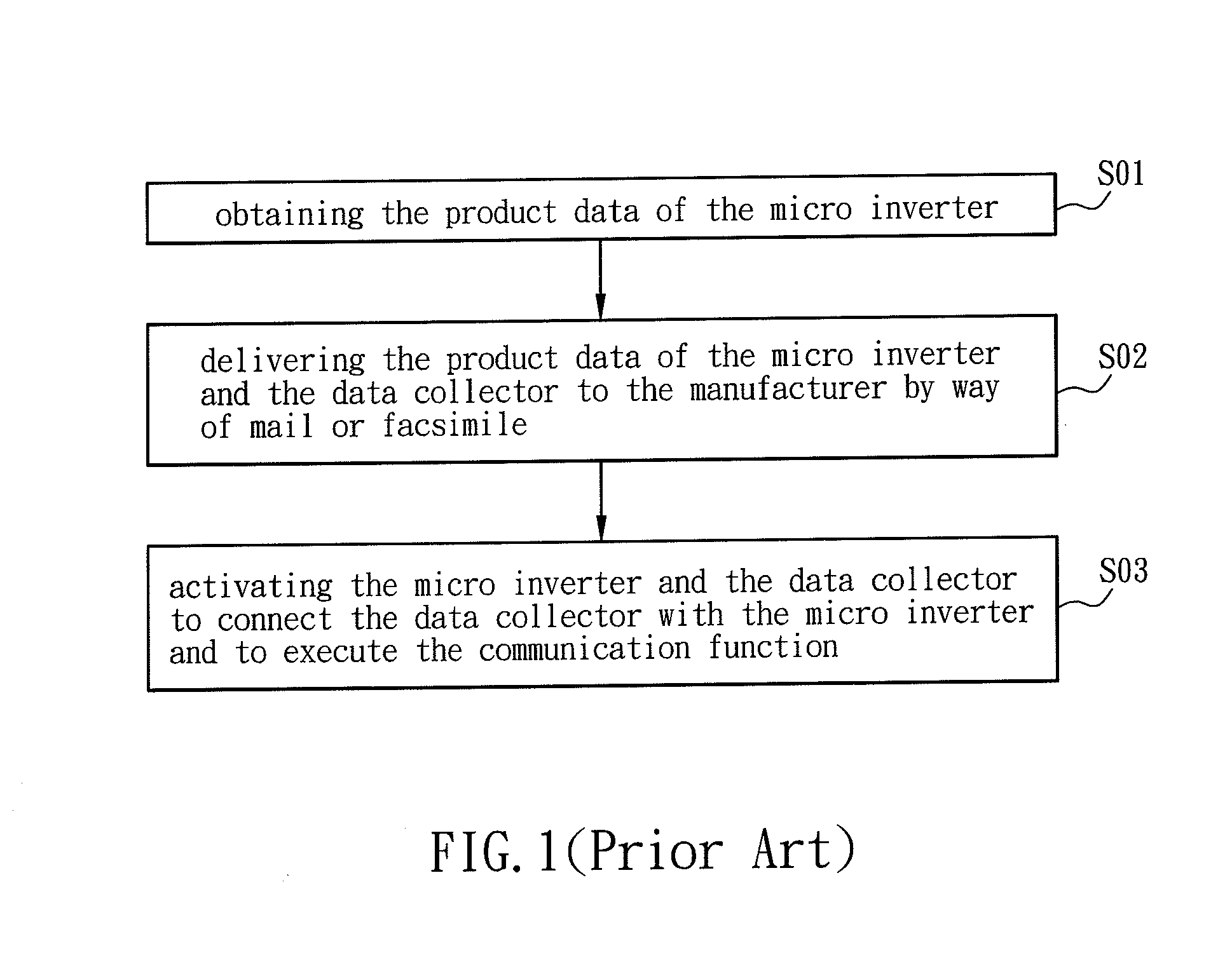
Although the conventional power line communication (PLC) method for activating the data collector and the micro inverter can let the manufacturer exactly obtain the used condition and used number, the excess manpower and time have to be wasted to deliver the product data of the micro inverter and the data collector, and the micro inverter and the data collector cannot be used immediately before being activated, thereby bringing a lot of inconvenience for the user.

Method used


Image

  • Power line communcation method and power line communication system
  • Power line communcation method and power line communication system
  • Power line communcation method and power line communication system

Examples


Embodiment Construction

[0035]The present invention will be apparent from the following detailed description, which proceeds with reference to the accompanying drawings, wherein the same references relate to the same elements.

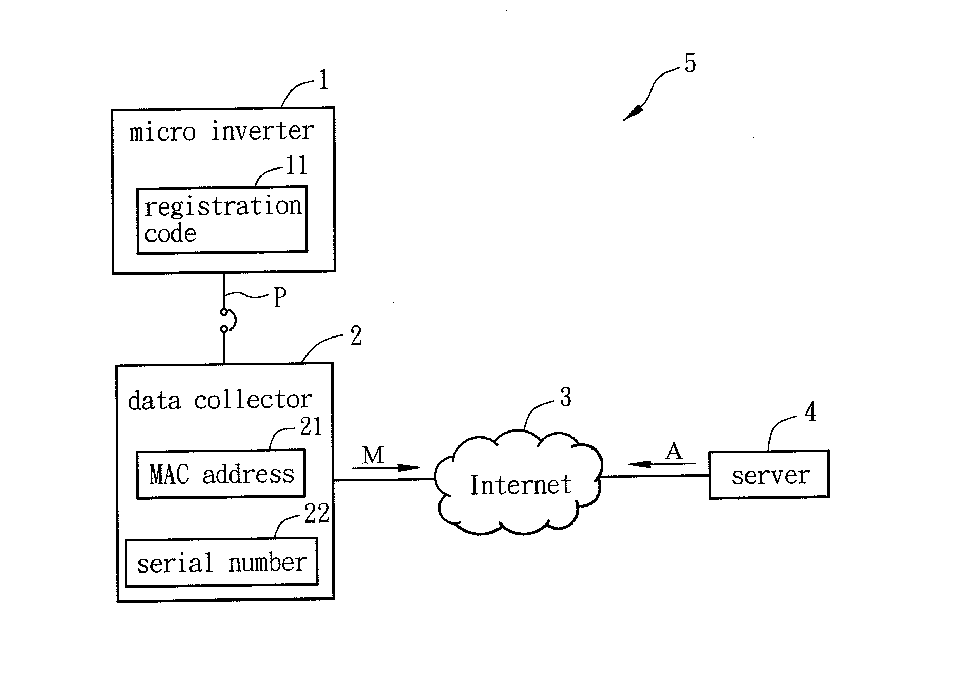
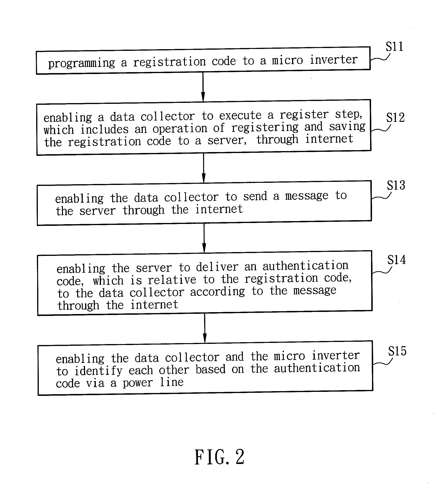
[0036]FIG. 2 is a flow chart showing steps of a power line communication (PLC) method according to a preferred embodiment of the invention, and FIG. 3 is a schematic illustration showing a PLC system according to a preferred embodiment of the invention. Referring simultaneously to FIGS. 2 and 3, a power line communication (PLC) method of this embodiment, which is mainly applied to the narrowband PLC, includes steps S11 to S15. A PLC system 5 of this embodiment includes a micro inverter (or microinverter) 1, a data collector 2 and a server 4. The micro inverter 1 of this embodiment is, for example, a solar energy micro inverter. In addition, the micro inverter 1 is connected with the data collector 2 via a power line P, and the data collector 2 is connected with the server 4 through in...


PUM


Abstract

A power line communication (PLC) method includes the steps of: programming a registration code into a micro inverter; enabling a data collector to execute a register step, which includes an operation of registering and saving the registration code to a server, through internet; enabling the data collector to send a message to the server through the internet; enabling the server to deliver an authentication code, which is relative to the registration code, to the data collector through the internet according to the message; and enabling the data collector and the micro inverter to identify each other via a power line based on the authentication code.

Description

CROSS REFERENCE TO RELATED APPLICATIONS[0001]This Non-provisional application claims priority under 35 U.S.C. §119(a) on Patent Application No(s). 201210026850.X filed in People's Republic of China on Feb. 8, 2012, the entire contents of which are hereby incorporated by reference.BACKGROUND OF THE INVENTION[0002]1. Field of Invention[0003]The invention relates to a communication method and system, and in particular, to a power line communication (PLC) method and a PLC system.[0004]2. Related Art[0005]The home network is the essential fundamental construction of the digital home, and the apparatuses in the future digital homes have the network connection functions. The power line communication (PLC) method is one of various methods of implementing the home network. The PLC represents a communication manner for transmitting data, video and audio signals via a power line, and has the transmission frequency bands, which may be divided into the narrowband communication and the broadband ...

Claims


Application Information

Patent Timeline
IPC IPC(8): H04B3/54H04L12/56
CPCH04B3/542H04B2203/5445H04B2203/5408
Inventor LI, SHENG-HUADAI, CHI-HSIUNGCHEN, HAO-HSUANCHANG, CHIA-WEI
Owner DELTA ELECTRONICS INC
Why Eureka
Eureka Blog
Learn More