Height Adjustable Phase Plate for Generating Optical Vortices

a phase plate and adjustable technology, applied in the field of height adjustable phase plate for generating optical vortices, can solve the problems of not allowing the topological charge to be changed, the reflective plate does not allow information to be encoded,

Inactive Publication Date: 2013-01-31
SELEX SISTEMI INTEGRATI
View PDF1 Cites 113 Cited by
  • Summary
  • Abstract
  • Description
  • Claims
  • Application Information

AI Technical Summary

Problems solved by technology

The SPP 1 therefore has the disadvantage of not allowing the topological charge to be changed.
However, the reflective plate does not allow informatio

Method used


Image

  • Height Adjustable Phase Plate for Generating Optical Vortices
  • Height Adjustable Phase Plate for Generating Optical Vortices
  • Height Adjustable Phase Plate for Generating Optical Vortices

Examples


Embodiment Construction

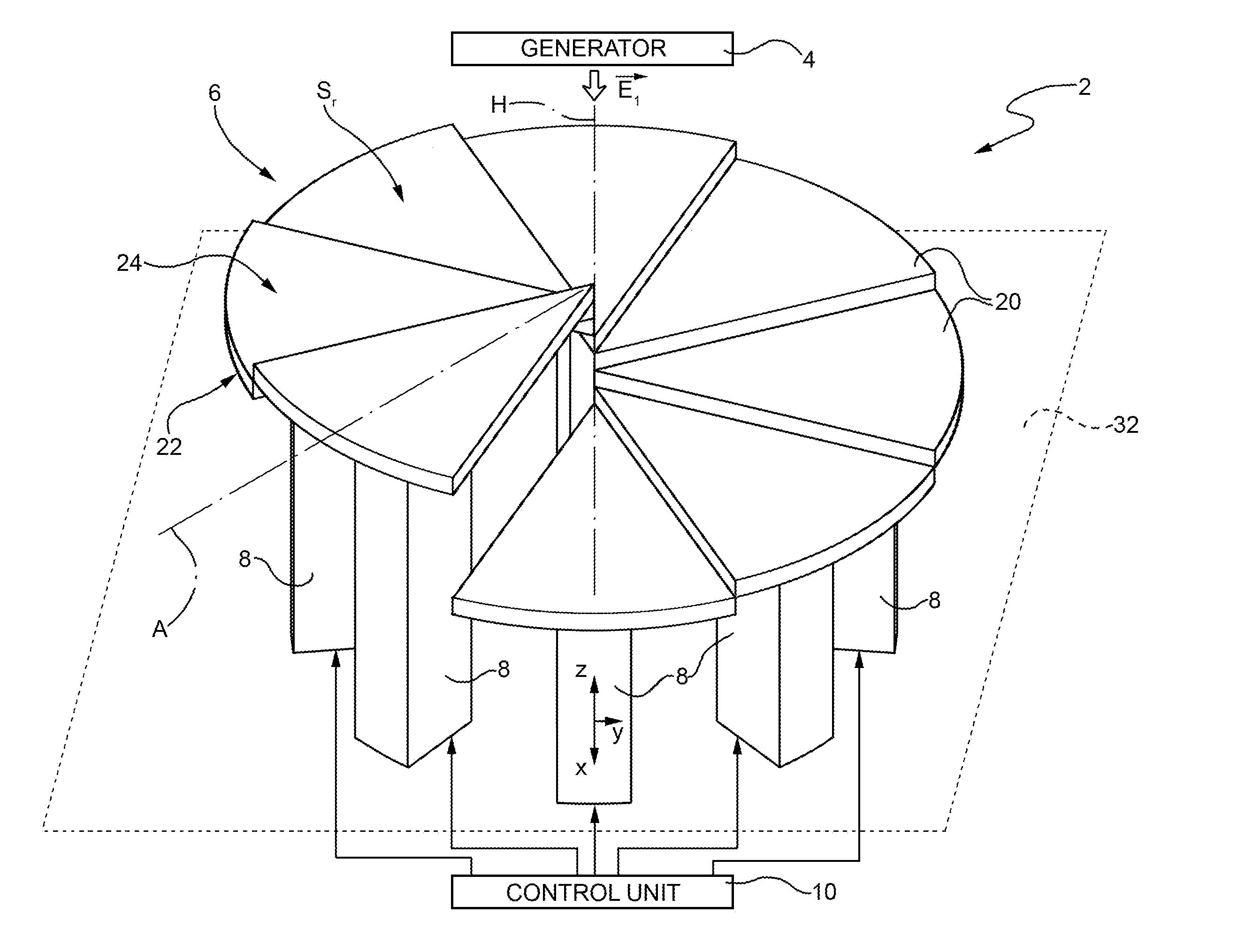
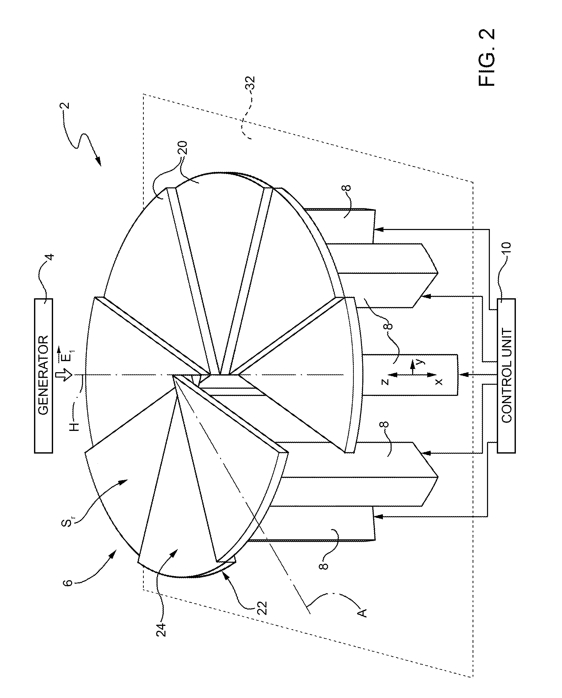
[0027]FIG. 2 shows an optical vortex generator 2, which comprises an electromagnetic field generator 4, a phase plate 6, a plurality of actuators 8 and a control unit 10.

[0028]In detail, the electromagnetic field generator 4 generates a first electromagnetic field E1 with wavelength λ and any type of polarization, but with null orbital angular momentum. Purely by way of example, the wavelength λ could be 830 nm.

[0029]The phase plate 6 comprises a plurality of elementary units 20, arranged around a symmetry axis H and made of a conducting material such as, for example, silver or gold. In addition, the number of actuators 8, which, for example are of the piezoelectric type, is equal to the number of elementary units 20.

[0030]Each elementary unit 20 is mechanically coupled to a corresponding actuator 8. In particular, under the action of the corresponding actuator 8, as described further on, each elementary unit 20 is mobile parallel to the symmetry axis H.

[0031]In greater detail, the ...


PUM


Abstract

A phase plate including a plurality of surfaces arranged around a symmetry axis to reflect an incident electromagnetic field having a null orbital angular momentum, thereby generating a reflected electromagnetic field having an orbital angular momentum. The surfaces are arranged such that, with respect to a cylindrical reference system in which the azimuthal coordinate is measured in a plane perpendicular to the symmetry axis, the respective heights define a non-monotonic azimuthal profile, so that the reflected electromagnetic field forms an optical vortex whose topological charge is not associated one-to-one to the orbital angular momentum.

Description

[0001]The present invention relates to a height-adjustable phase plate for generating optical vortices.BACKGROUND OF THE INVENTION[0002]As is known, given an electromagnetic field in space, the location of the points in space where the electromagnetic field has null amplitude defines a so-called phase singularity, also known as phase dislocation. By way of example, various types of phase dislocation are known, such as, for example, screw dislocation, edge dislocation or mixed screw-edge dislocation.[0003]Electromagnetic vortices, also known as so-called optical vortices, are also known. In general, the electromagnetic field defines an optical vortex when it has a dot-like phase singularity, around which the phase of the electromagnetic field itself is wrapped, creating a structure with helical phase fronts. Furthermore, the presence of one or more optical vortices is indicative of the fact that the electromagnetic field defines a location of points in space where it has null amplitu...

Claims


Application Information

Patent Timeline
IPC IPC(8): G02B5/30
CPCG02B26/06G02B27/286G02B26/0858
Inventor BOVINO, FABIO A.BRACCINI, MATTEO
Owner SELEX SISTEMI INTEGRATI
Why Eureka
Try Eureka