
Inter-plane prediction

a prediction and plane technology, applied in the field of image and video coding, can solve the problems of large number of small blocks, large number of pictures, and limited sub-divided picture (or plane group) into blocks provided by the syntax

Active Publication Date: 2013-02-07
GE VIDEO COMPRESSION LLC
View PDF16 Cites 194 Cited by
  • Summary
  • Abstract
  • Description
  • Claims
  • Application Information

AI Technical Summary

Benefits of technology

The patent describes a method for generating a data stream that represents different spatially sampled information components of a picture of a scene in planes. The method involves determining coding parameters for each sample and inter-plane interchange information for corresponding samples in a second array. The coding parameters are then inserted into the data stream. The patent also describes a method for performing a spatial sub-division of the samples based on two subsets of syntax elements and merging the sub-divisions to obtain a plurality of simply connected regions. This allows for a better adaptation to the actual content of the two-dimensional information signal and reduces the impact of the merging on the rendering process.

Problems solved by technology

In image and video coding standards, the possibilities for sub-dividing a picture (or a plane group) into blocks that are provided by the syntax are very limited.
The small set of possibilities for specifying the partitioning into blocks in state-of-the-art image and video coding standards has the advantage that the side information rate for signaling the sub-division information can be kept small, but it has the disadvantage that the bit rate that may be used for transmitting the prediction parameters for the blocks can become significant as explained in the following.
For arbitrarily shaped objects this can result in a large number of small blocks.
On the other hand, setting the coding parameters at a finer granularity poses a higher burden onto the amount of side information useful in order to inform the decoder on the useful settings.
Even further, it should be noted that any freedom for the encoder to (further) sub-divide the picture / video spatially into blocks tremendously increases the amount of possible coding parameter settings and thereby generally renders the search for the coding parameter setting leading to the best rate / distortion compromise even more difficult.
For example, if the maximum region size is high, the multi-tree sub-division information is likely to get more complex due to the treeroot regions getting larger.

Method used


Image

  • Inter-plane prediction
  • Inter-plane prediction
  • Inter-plane prediction

Examples


Embodiment Construction

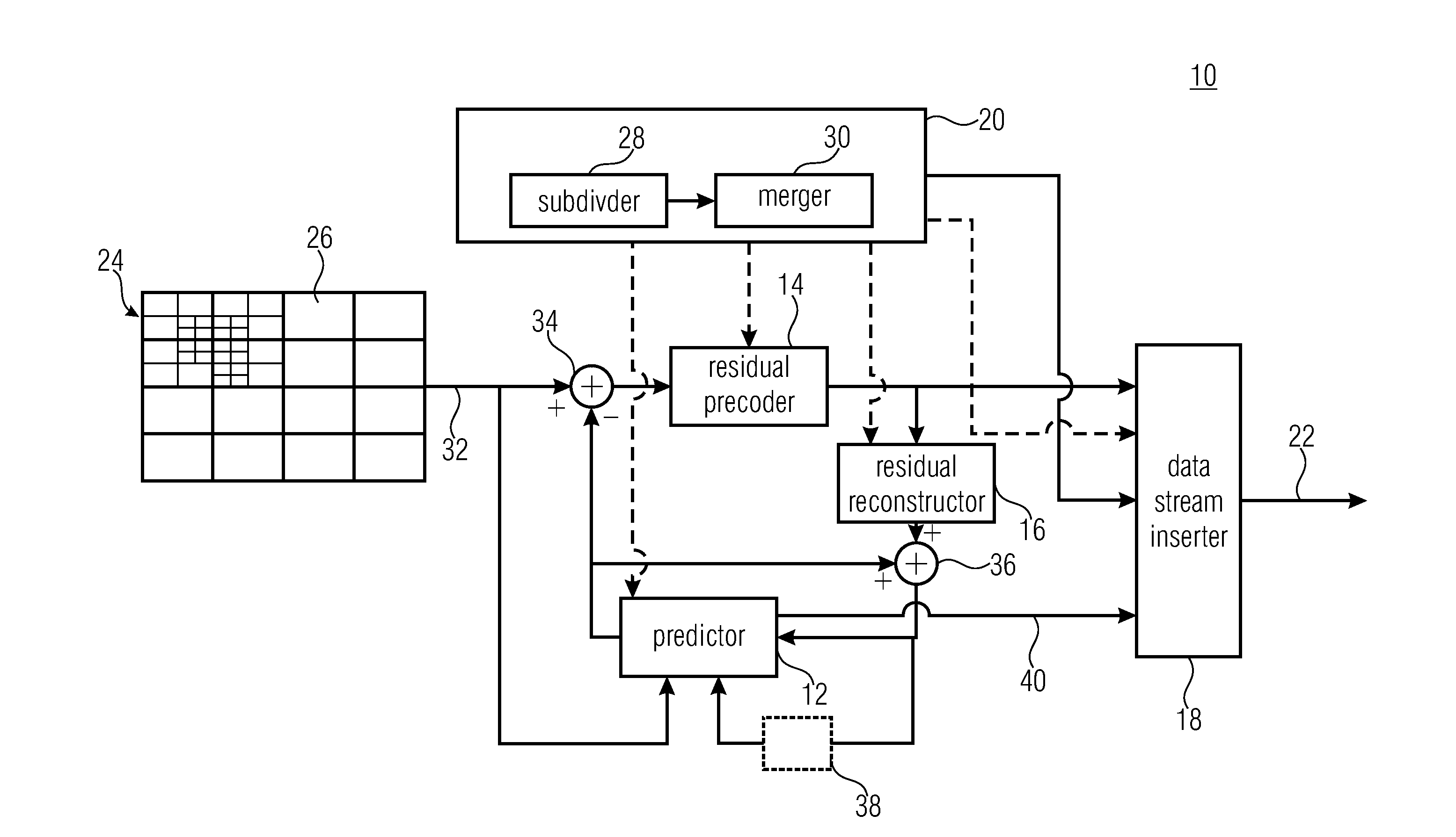
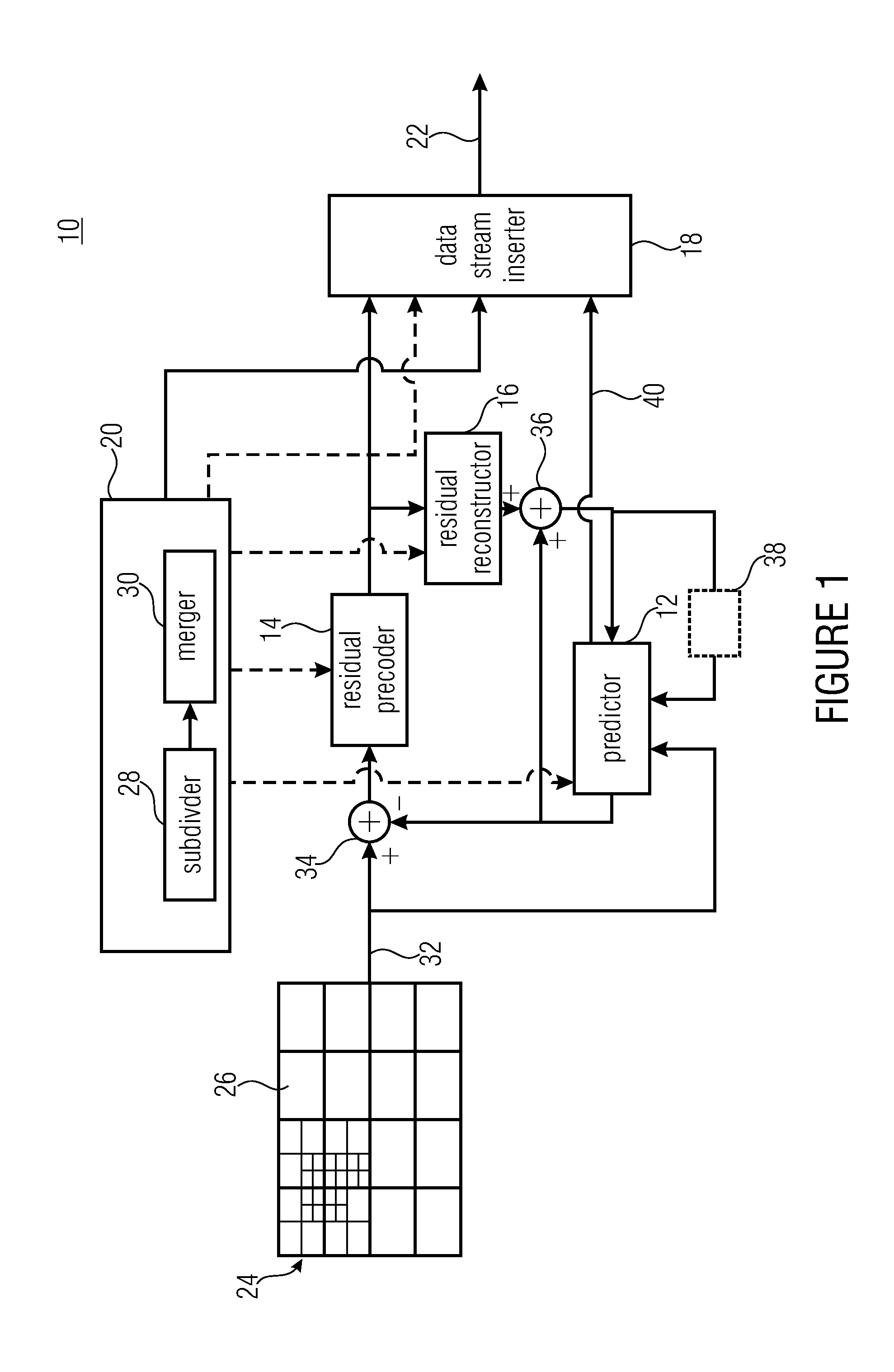
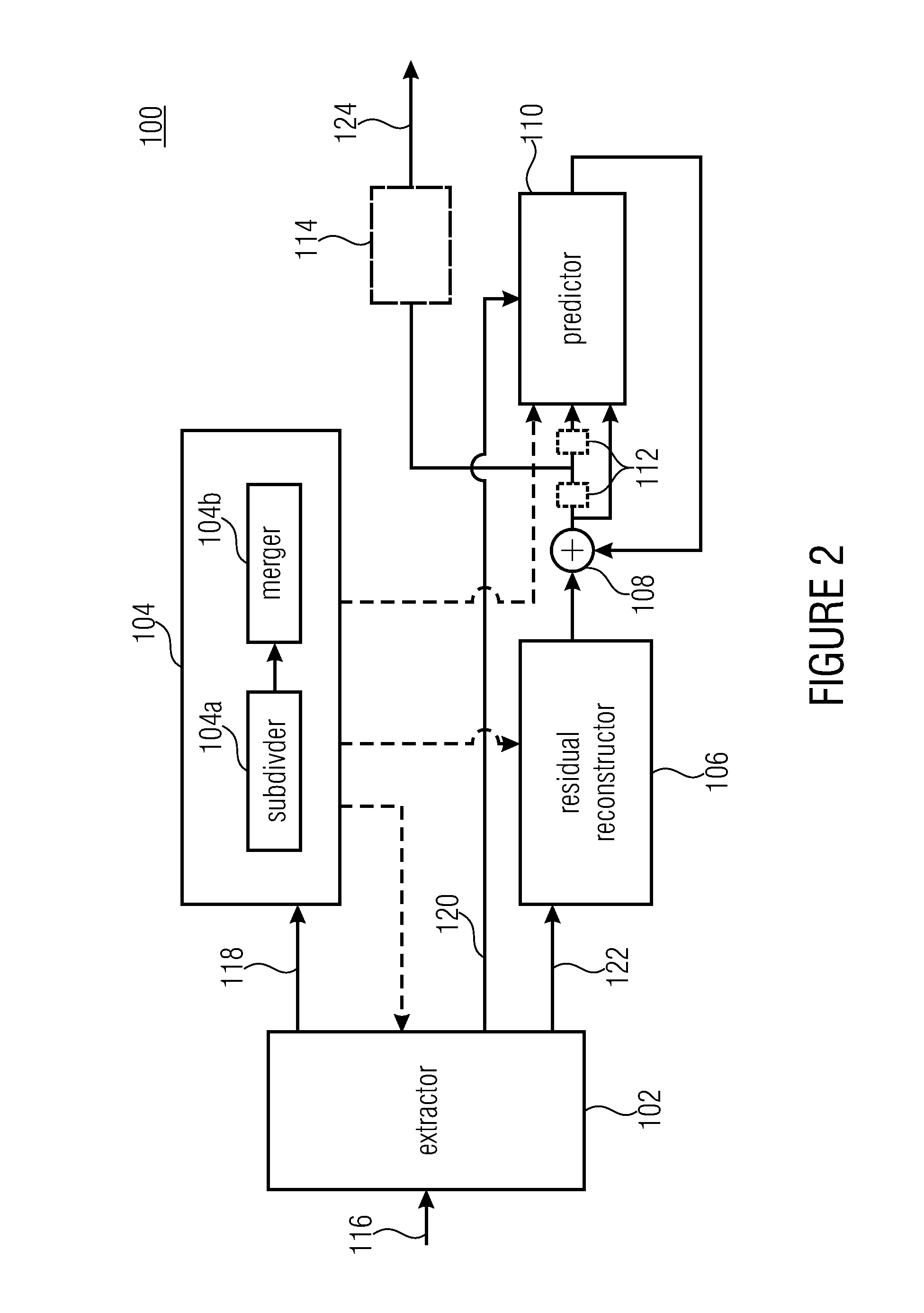
[0057]In the following description of the Figs., elements occurring in several of these Figs. are indicated by common reference numbers and a repeated explanation of these elements is avoided. Rather, explanations with respect to an element presented within one Fig. shall also apply to other Figs. in which the respective element occurs as long as the explanation presented with these other Figs. indicate deviations therefrom.

[0058]Further, the following description starts with embodiments of an encoder and decoder which are explained with respect to FIGS. 1 to 11. The embodiments described with respect to these Figs. combine many aspects of the present application which, however, would also be advantageous if implemented individually within a coding scheme and accordingly, with respect to the subsequent Figs., embodiments are briefly discussed which exploit just-mentioned aspects individually with each of these embodiments representing an abstraction of the embodiments described with...


PUM


Abstract

A better rate distortion ratio is achieved by making interrelationships between coding parameters of different planes available for exploitation for the aim of redundancy reduction despite the additional overhead resulting from the need to signal the inter-plane prediction information to the decoder. In particular, the decision to use inter plane prediction or not may be performed for a plurality of planes individually. Additionally or alternatively, the decision may be done on a block basis considering one secondary plane.

Description

CROSS-REFERENCE TO RELATED APPLICATIONS[0001]This application is a continuation of copending International Application No. PCT / EP2010 / 054840, filed Apr. 13, 2010, which is incorporated herein by reference in its entirety.[0002]The present invention relates to coding schemes for different spatially sampled information components of a picture of a scene, provided in planes, each plane comprising an array of information samples, such as in videos or still pictures.BACKGROUND OF THE INVENTION[0003]In image and video coding, the pictures or particular sets of sample arrays for the pictures are usually decomposed into blocks, which are associated with particular coding parameters. The pictures usually consist of multiple sample arrays. In addition, a picture may also be associated with additional auxiliary samples arrays, which may, for example, specify transparency information or depth maps. The sample arrays of a picture (including auxiliary sample arrays) can be grouped into one or mor...

Claims


Application Information

Patent Timeline
IPC IPC(8): H04N7/12
CPCH04N19/597H04N19/176H04N19/70H04N19/119H04N19/147H04N19/186H04N19/196H04N19/61H04N19/96H04N19/103H04N19/463H04N19/46H04N19/11H04N19/132H04N19/105H04N19/52H04N19/159
Inventor WINKEN, MARTINKIRCHHOFFER, HEINERSCHWARZ, HEIKOMARPE, DETLEVWIEGAND, THOMAS
Owner GE VIDEO COMPRESSION LLC
Learn More