Finger board

a fingerprint recognition and finger board technology, applied in the field of finger boards, can solve the problems of difficult assembly, high assembly cost, and difficulty in forming micro-structures on the light guiding plate, and achieve the effects of simplifying the assembly procedure of the fingerprint recognition apparatus, reducing assembly cost, and improving fingerprint recognition ra

Inactive Publication Date: 2013-02-07
GINGY TECH
View PDF17 Cites 23 Cited by
  • Summary
  • Abstract
  • Description
  • Claims
  • Application Information

AI Technical Summary

Benefits of technology

[0011]In the finger board according to the present disclosure, a plurality of micro-structures is employed to make the light ray be uniformly distributed on the finger board. Therefore, the finger is illuminated by the uniform and dense light ray emitted form the finger board, and thereby, the fingerprint recognition rate is improved.
[0012]Moreover, the finger board comprises multiple layers with different refractive indexes so a part of the light ray entering the finger board is reflected and another part of the light ray entering the finger board is scattered. Therefore, a fingerprint recognition apparatus employing the finger board of the present disclosure does not need to restrict the installation position and angle of other devices, thereby simplifying an assembly procedure of the fingerprint recognition apparatus, reducing the assembly cost, and making the fingerprint recognition apparatus even thinner. In addition, the micro-structure layer of the finger board according to the present disclosure may be formed by rolling screen printing, thereby saving the cost of molds.

Problems solved by technology

Therefore, the assembly is difficult, and the cost of the assembly is high, which is not economical.
However, since the light guiding plate is manufactured by injection molding, formation of the micro-structures on the light guiding plate is not easily.
Accordingly, different mould needs to be made to fabricate a light guiding plate having a different micro-structures arrangement, and thereby, the production cost is increased.

Method used


Image

  • Finger board
  • Finger board
  • Finger board

Examples


Embodiment Construction

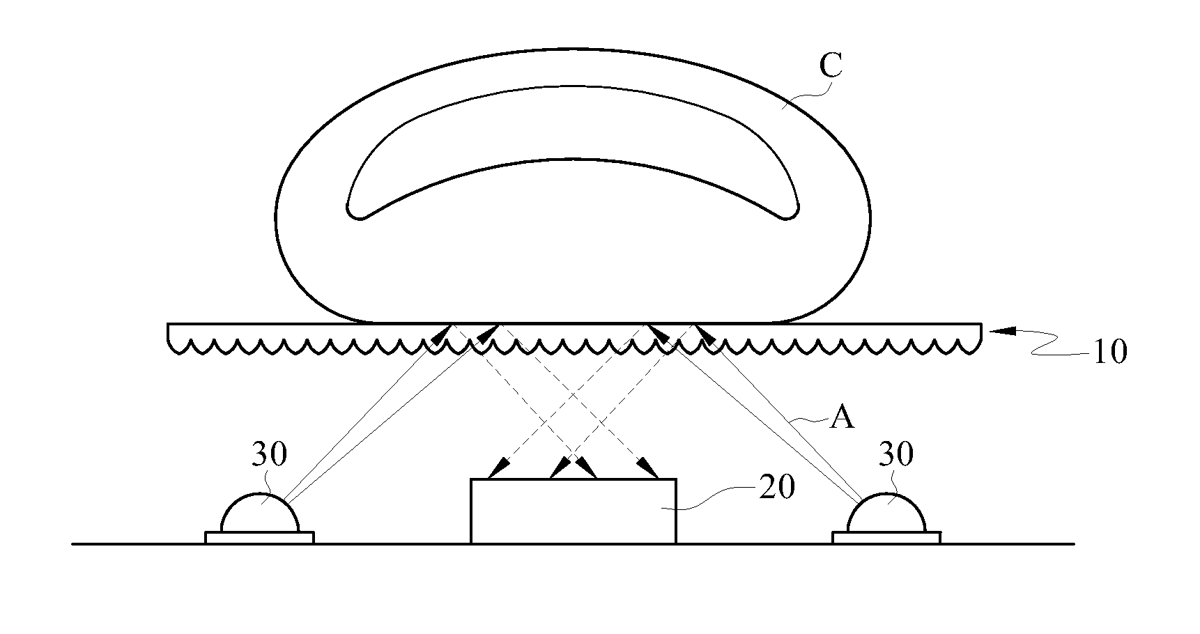
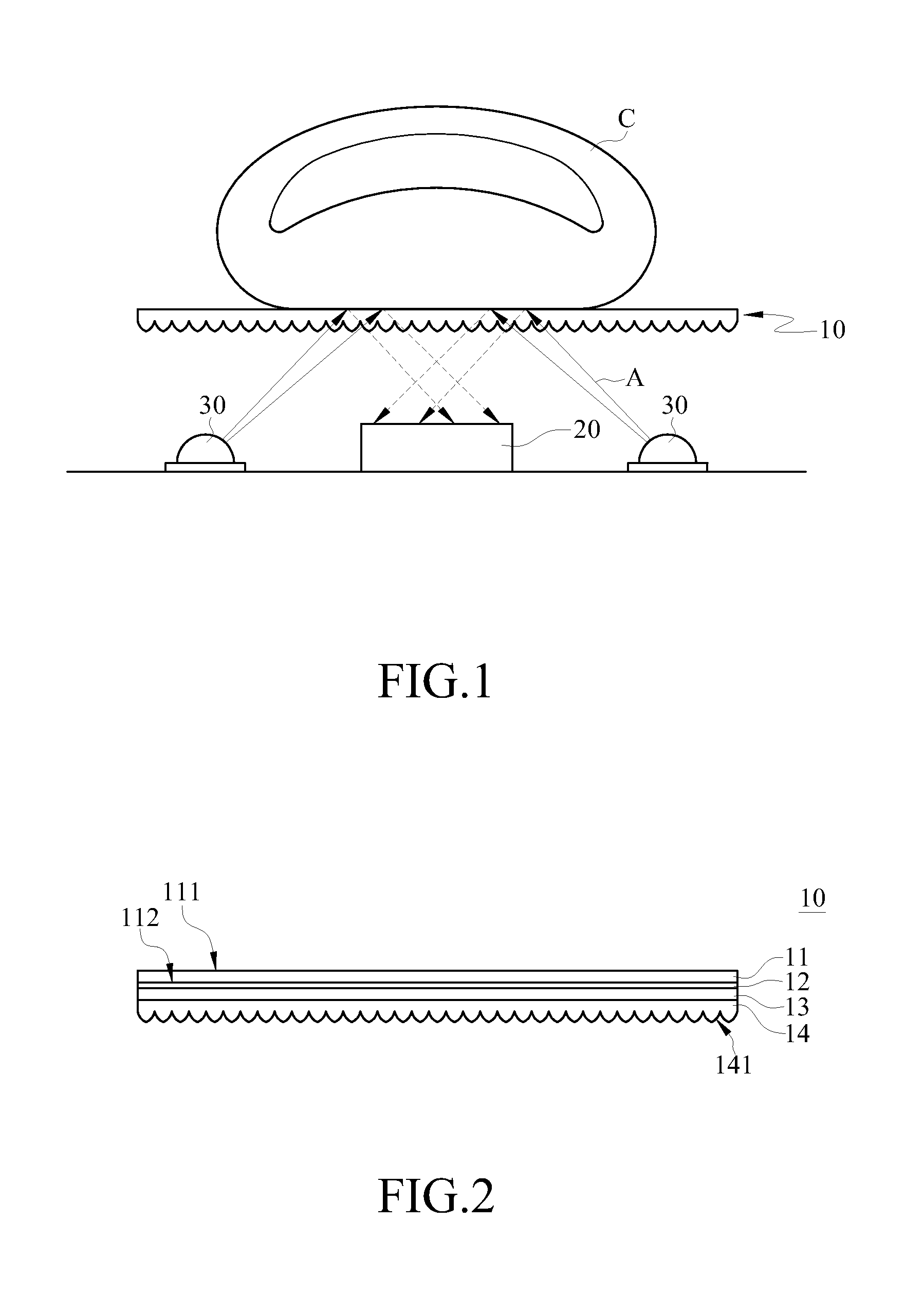
[0022]FIG. 1 is a schematic structural view of a fingerprint recognition apparatus according to an embodiment. FIG. 2 is a structural sectional view of a finger board according to an embodiment.

[0023]Referring to FIG. 1 and FIG. 2, the finger board 10 of this embodiment is applied to the fingerprint recognition apparatus. The fingerprint recognition apparatus comprises the finger board 10, an imaging device 20, and at least one light emitting device 30. When a finger C is placed on the finger board 10, the light emitting device 30 may be driven to emit a light ray A towards the finger board 10. The light ray A enters the finger board 10 and irradiates the finger C, and a fingerprint pattern with light and shade portions is generated. Thus the imaging device 20 is capable of capturing and recognizing fingerprints. In the drawing, the path of the light ray A is only taken as an example, and not intended to limit the present disclosure.

[0024]The finger board 10 comprises a board layer ...


PUM


Abstract

A finger board for a finger to press including a board layer and a micro-structure layer is disclosed. The board layer has a first refractive index, and has a first board surface and a second board surface opposite to each other. The first board surface is used for the finger to press. The micro-structure layer has a second refractive index different from the first refractive index, and is disposed on the second board surface. Therefore, a light ray emitted from the micro-structure layer to the first board surface can be reflected and scattered on the first board surface, so as to uniformly distribute energy.

Description

CROSS-REFERENCE TO RELATED APPLICATIONS[0001]This non-provisional application claims priority under 35 U.S.C. §119(a) on Patent Application No(s). 100128073 filed in Taiwan, R.O.C. on Aug. 5, 2011, the entire contents of which are hereby incorporated by reference.BACKGROUND[0002]1. Technical Field[0003]The present disclosure relates to a finger board, and more particularly to a finger board applicable to a fingerprint recognition apparatus.[0004]2. Related Art[0005]A conventional fingerprint input apparatus comprises an imaging device, a light guiding plate disposed above the imaging device, and two light emitting devices disposed on two sides of the light guiding plate. When the light emitting device emits light, the light guiding plate guides incident light to project onto a finger and then a total internal reflection occur while the light is reflected from the finger to the imaging device. Accordingly, the fingerprint is recognized.[0006]However, since the total internal reflecti...

Claims


Application Information

Patent Timeline
Patent Type & Authority Applications(United States)
IPC IPC(8): G06K9/00
CPCG06K9/00046G06V40/1324G06V10/40
Inventor WU, CHIEN-HSINGCHOU, JUNG-TSUNG
Owner GINGY TECH
Why Eureka
Try Eureka