Toroidal continuously variable transmission

a transmission and continuous variable technology, applied in the direction of friction gearings, gearing elements, friction gearings, etc., can solve the problems of difficult to maintain sufficient reliability, difficult to lower cost, vibration, etc., and achieve easy manufacturing, management and assembly work of parts, and improve the durability of support beam sections.

Inactive Publication Date: 2013-02-07
NSK LTD
View PDF1 Cites 97 Cited by
  • Summary
  • Abstract
  • Description
  • Claims
  • Application Information

AI Technical Summary

Benefits of technology

[0082]In the case of the toroidal continuously variable transmission of the first aspect of the present invention, when the support beam sections of the trunnions elastically deform due to a thrust load that is applied to the power rollers from the input and output disks during operation, the cylindrical convex surfaces that are formed on the inside surfaces of these support beam sections will tend to coincide with the concave sections that are formed on the outer rings of the thrust bearings, or in other words, there will be a tendency for contact over a sufficiently wide range. Therefore, it is possible to keep the contract pressure that is applied at the areas of contact between the cylindrical convex surfaces and the concave sections during operation low, and thus it is possible to improve the durability of the support beam sections and the outer rings.
[0083]In the case of the toroidal continuously variable transmission of the second through fourth aspects of the present invention, ...

Problems solved by technology

However, in the former construction, it is difficult to support and fasten the anchor piece by the support beam section such that strength and rigidity capable of supporting the force 2Ft, and it is difficult to lower cost and maintain sufficient reliability.
Moreover, in the case of the latter construction, the force 2Ft becom...

Method used


Image

  • Toroidal continuously variable transmission
  • Toroidal continuously variable transmission
  • Toroidal continuously variable transmission

Examples


embodiment 1

Example 2

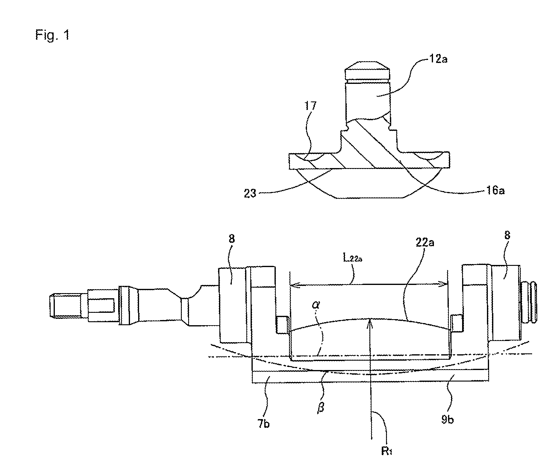
[0127]FIG. 2 illustrates a second example of the first embodiment of the present invention. A feature of this example is the shape of the concave section 23a that is formed on the outside surface (bottom surface in FIG. 2) of the outer ring 16b of the thrust ball bearing for supporting a thrust load that is applied to the power roller 6a (FIG. 35 and FIG. 36). The basic construction and functions of the other parts are the same as in the second example of conventional construction.

[0128]In this example, the concave section 23a is not a simple cylindrical concave surface, but as exaggeratedly illustrated in FIG. 2, crowning is provided for the entire concave section 23a. More specifically, the shape of the generating line of the entire concave section 23a, which is the portion where crowning is provided, is such that, as exaggeratedly illustrated in FIG. 2, the center section is a simple arc shape that protrudes the most in toward the outside (bottom side in FIG. 2) in the r...

embodiment 2

Example 2

[0143]FIG. 13 and FIG. 14 illustrate a second example of the second embodiment of the present invention. In this example, support holes 28a having a circular cross section and having a bottom are formed at two locations in both end sections in the width direction of the concave section 23f that is formed on the outside surface of the outer ring 16g. The positions where these support holes 28a are formed are positions that coincide with each other in the axial direction of the center axis of the concave section 23f (positions on the same circumference). The directions of these support holes 28a are in the same direction (parallel) as the direction of the center axis of the support shaft 12a that is formed on the inside surface of the outer ring 16g. The base side half section of anchor pins 26a are pressure fitted into these support holes 28a with an interference fit, such that these anchor pins 26a are fastened to the outer ring 16g. The portions on the tip side half sectio...

embodiment 3

Example 4

[0164]FIG. 26 illustrates a fourth example of a third embodiment of the present invention. In this example, the flat surface 45a that is formed on the outer circumferential surface of the outer ring 16k for installing the spring holder 44a is inclined in the radial direction of the outer ring 16k. More specifically, the flat surface 45a is formed in the tangential direction with respect to the outer circumferential surface of the outer ring 16k, however, is inclined in a direction such that the space that is formed between the flat surface 45a and the one stepped surface 25 that is formed in the trunnion 7a becomes wider going toward the side of the support beam section 9a. The one surface of the spring holder 44a that is placed between the flat surface 45a and the stepped surface 25 is also inclined in the same direction. With the construction of this example, the holder 44a is prevented from coming out from between the flat surface 45a and the stepped surface 25 in a dire...


PUM


Abstract

The present invention achieves construction of a toroidal continuously variable transmission of which manufacture, management and assembly of parts can be performed easily, reduction of cost is easy and speed change operation is stabilized. This construction comprises support holes 28 having a circular cross section that are formed in part of the outer rings 16f, column shaped anchor pins 26 that, when fitted and fastened inside the support holes 28 with an interference fit, part of the anchor pin 26 protrudes from the inside surface of a concave section 23e of the outer ring 16f, and anchor grooves 27 that are formed in cylindrical convex surfaces 22e of support beam sections 9f of the trunnions 7f in the circumferential direction of the cylindrical convex surfaces 22e; wherein, the engagement sections where the parts of the anchor pins 26 engage with the anchor grooves 27 can support torque that is applied to the power rollers 6a as the input and output disks 2, 5 rotate.

Description

TECHNICAL FIELD[0001]The present invention relates to a half toroidal continuously variable transmission that is used as an automatic transmission.BACKGROUND ART[0002]Half toroidal continuously variable transmissions are already widely used as transmissions for automobiles for example, and construction of such a transmission is disclosed in JP2003-214516(A), JP2007-315595(A), JP2008-25821(A) and JP2008-275088(A). Moreover, construction for increasing the adjustable range of transmission ratios by combining a toroidal continuously variable transmission with a planetary gear mechanism is known and disclosed in JP2004-169719(A), JP2009-30749(A) and JP2006-283800(A). FIG. 28 and FIG. 29 illustrate a first example of a conventional toroidal continuously variable transmission. In this toroidal continuously variable transmission, a pair of input disks 2 are supported around the portions near both ends of an input rotating shaft 1, such that the inside surfaces, which are toroid surfaces fa...

Claims


Application Information

Patent Timeline
IPC IPC(8): F16H15/36
CPCF16H15/38F16H63/065
Inventor NOJI, SACHIKOINOUE, TOMOHIRONISHII, HIROKIYAMAGUCHI, TOMOMITOYODA, TOSHIROKISHIDA, HIROTAKA
Owner NSK LTD
Why Eureka
Try Eureka