
Means and method for monitoring the flow of fluid

a technology of fluid flow and flow rate, applied in the direction of liquid/fluent solid measurement, volume/mass flow by electromagnetic flowmeter, instruments, etc., can solve the problems of limited use, conventional electromagnetic flow meters can only measure the average flow rate of conducting fluid, and conventional electromagnetic flow meters are generally only effective, etc., to achieve the effect of cheaper manufacture and operation

Active Publication Date: 2013-02-14
UNIVERSITY OF HUDDERSFIELD
View PDF21 Cites 19 Cited by
  • Summary
  • Abstract
  • Description
  • Claims
  • Application Information

AI Technical Summary

Benefits of technology

The invention is an electromagnetic flow meter and method that can accurately monitor the flow of a conducting fluid with a uniform or non-uniform flow profile. Compared to conventional flow meters, the invention has a lower error margin of approximately + / −0.5% for non-uniform fluids. Additionally, the invention is a low-cost solution that is cheaper to manufacture and operate than conventional flow meters.

Problems solved by technology

Although conventional electromagnetic flow meters are widely used it is recognised that they have a number of limitations.
For example, conventional electromagnetic flow meters can only measure the average flow rate of a conducting fluid—they can not determine the axial velocity profile of a conducting fluid.
Moreover, conventional electromagnetic flow meters are generally only effective when the conducting fluid has a uniform flow profile—they are unsuitable and / or inaccurate when the conducting fluid has a non-uniform flow profile.
Unfortunately, non-uniform flow conditions are often encountered.
A multiphase fluid may have a non-uniform flow profile if the component parts have different flow characteristics.
However, this type of flow meter does not provide information on the axial velocity profile of the fluid.
This can be a major drawback, particularly in multiphase fluids where, for example, the volumetric flow rate of a particular phase can only be found by integrating the product of the local phase velocity and the local phase volume fraction in the flow cross section.
As a result, the approach proposed by Horner can not be used to determine the flow rate of the conducting continuous phase of a multiphase fluid with a non-uniform flow profile.
Other known types of flow meters that are suitable for measuring the flow rate of a conducting phase of a multiphase fluid are constrained by high cost and the use of hazardous radioactive sources to monitor the flow.

Method used


Image

  • Means and method for monitoring the flow of fluid
  • Means and method for monitoring the flow of fluid
  • Means and method for monitoring the flow of fluid

Examples


Embodiment Construction

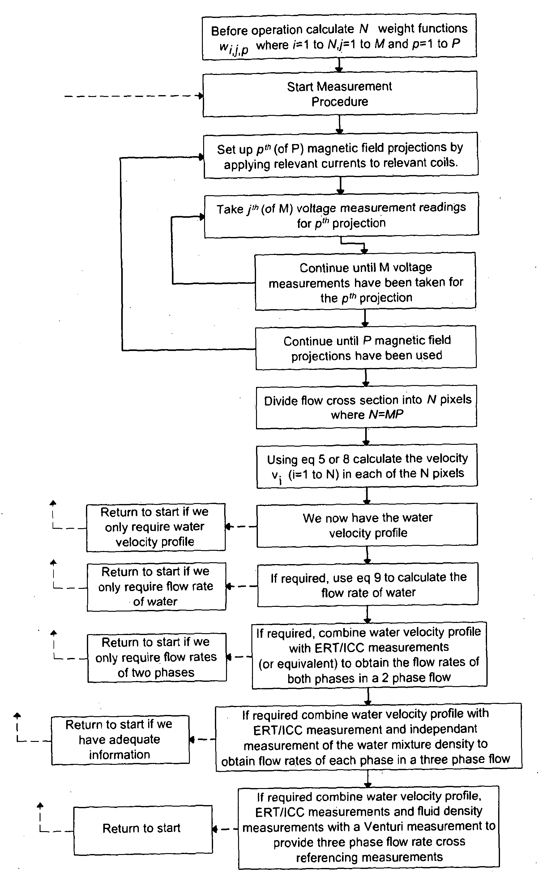
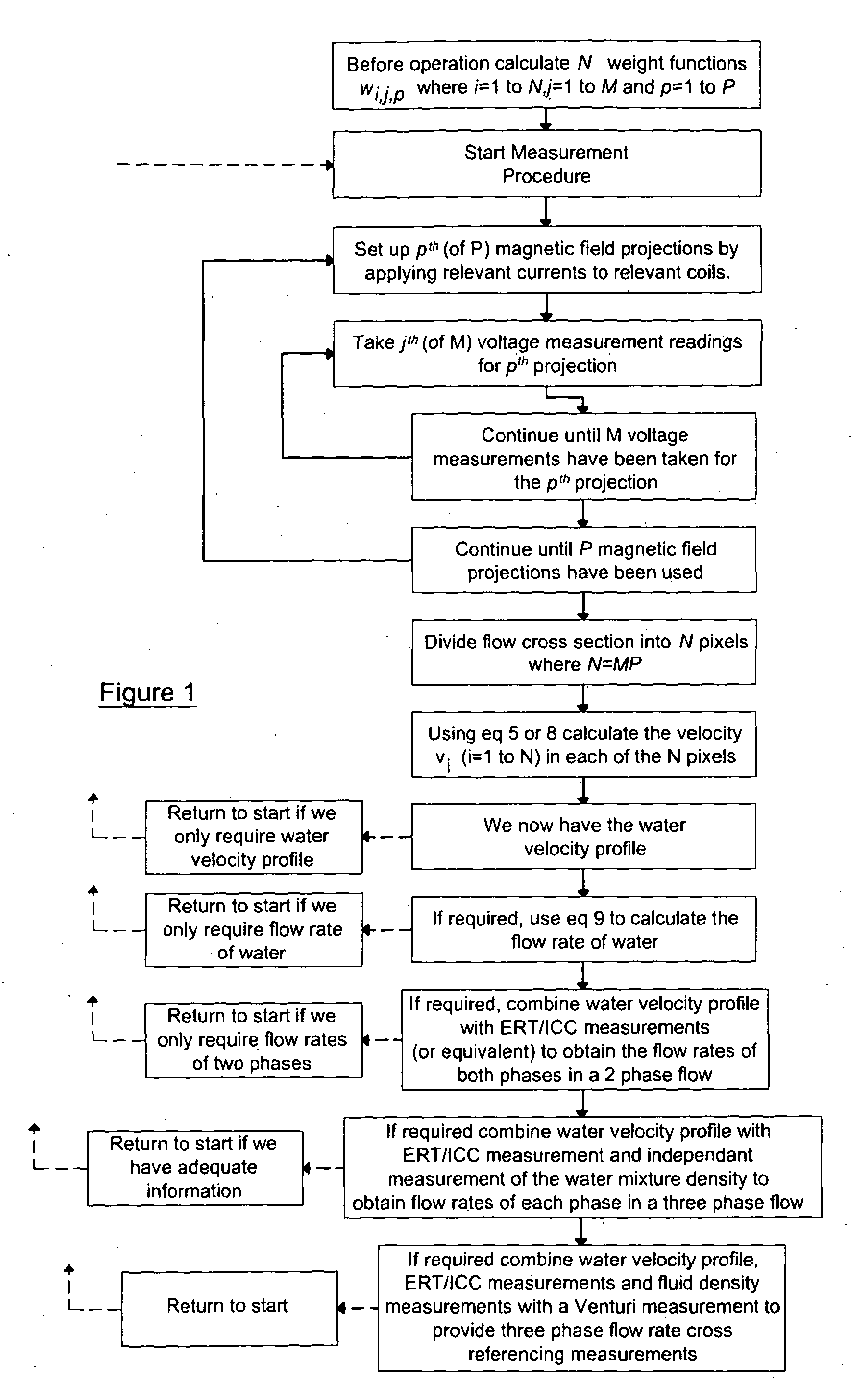
1. Determining the Axial Velocity Profile of a Conducting Fluid

[0065]The invention relates to an electromagnetic flow meter and method for monitoring the flow of a conducting fluid. As part of the monitoring process, the flow meter and method determine the axial velocity profile of a conducting fluid. The conducting fluid may be a conducting single phase fluid or a conducting continuous phase of a multiphase fluid. The conducting fluid may have a uniform flow profile or a non-uniform flow profile.

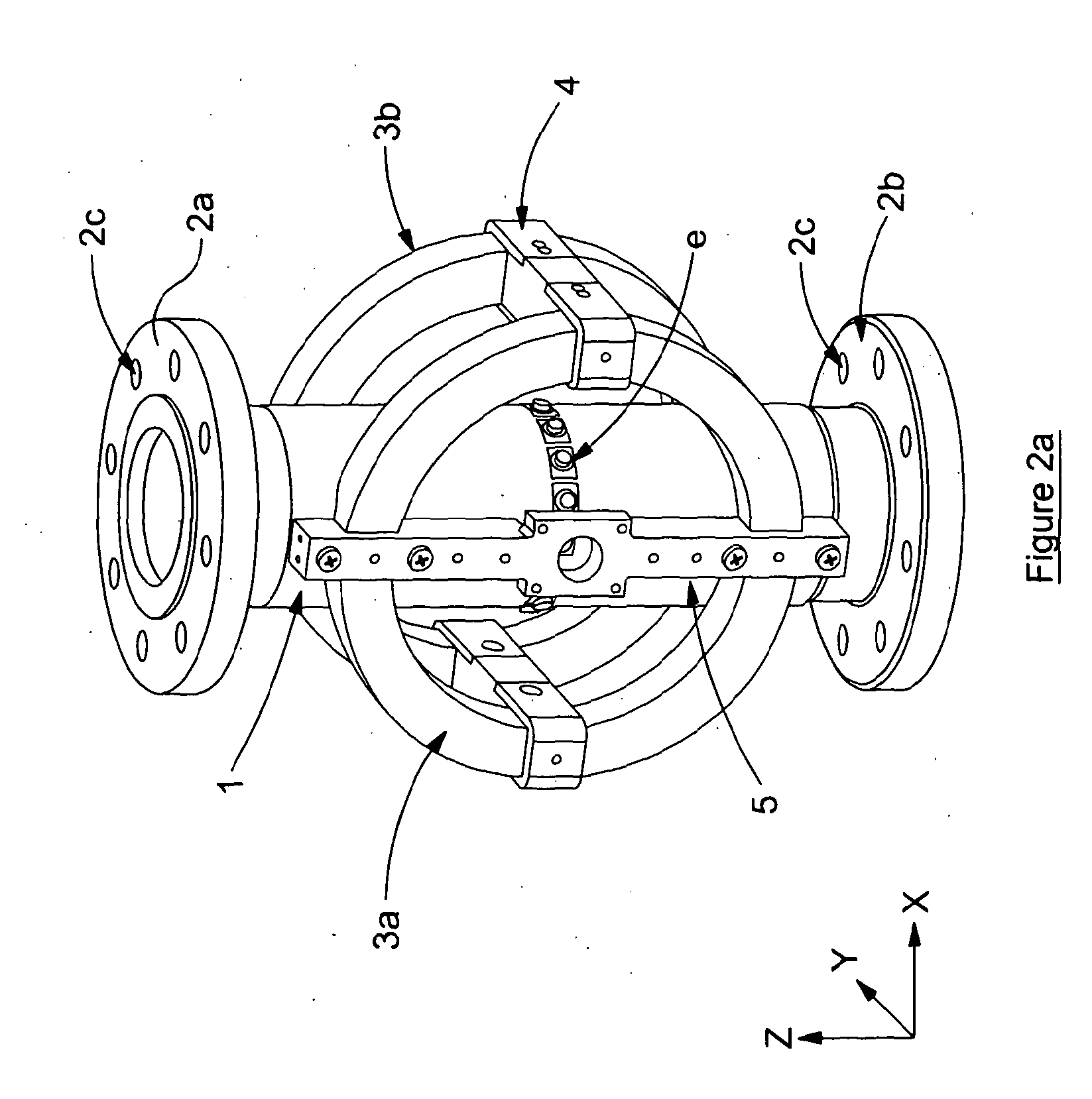
[0066]In its simplest form, the flow meter comprises a flow tube, a means for generating a magnetic field across the flow tube cross-section, an array of voltage detection electrodes circumferentially arranged around the flow tube and processing means for determining the axial velocity profile of a conducting fluid.

[0067]The flow tube is a pipe along which fluid can flow when the flow meter is in use. As mentioned above, the fluid may be a conducting single phase fluid or a multiphase fluid...


PUM


Abstract

The invention relates to an means and method for monitoring the flow of a fluid. The invention relates to an electromagnetic flow meter and method for measuring the axial velocity profile of a conducting fluid. The conducting fluid may be a conducting single phase fluid or a conducting continuous phase of a multiphase fluid. The conducting fluid may have a uniform flow profile or a non-uniform flow profile. The electromagnetic flow meter and method measure the axial velocity profile of a conducting fluid by dividing the flow cross section into multiple pixels and determining the axial velocity of the conducting fluid in each pixel. Having. derived the axial velocity profile, the electromagnetic flow meter and method may further derive the volumetric flow rate of the conducting fluid. The electromagnetic flow meter and method may be suitable for measuring the axial velocity profile and optionally the volumetric flow rates of each phase of a multiphase fluid.

Description

FIELD OF INVENTION[0001]The invention relates to a means and method for monitoring the flow of a fluid. The invention particularly relates to a means and method that is suitable for monitoring the flow of a fluid having a non-uniform flow profile.BACKGROUND TO THE INVENTION[0002]Electromagnetic flow meters are used in a variety of industries to monitor the flow of conducting fluids. Electromagnetic flow meters utilise Faraday's law of electromagnetic induction to induce a voltage in the conducting fluid as it moves through a magnetic field. The flow rate of the conducting fluid is then derived from the measured induced voltage.[0003]In a conventional electromagnetic flow meter the conducting fluid is directed to flow through a flow pipe, electromagnetic coils are located outside the flow pipe to create a magnetic field, two electrodes are mounted in the flow pipe wall to detect the induced voltage and processing means are configured to process the induced voltage data to determine t...

Claims


Application Information

Patent Timeline
IPC IPC(8): G01F1/58G01N33/00G01N9/04G01F1/74
CPCG01F1/588G01F1/74G01F1/712G01F1/60G01F1/586
Inventor LUCAS, GARY P.LEEUNGCULSATIEN, TEERACHAI
Owner UNIVERSITY OF HUDDERSFIELD
Learn More