Switch assembly

a technology of switch assembly and cover plate, which is applied in the direction of contact, tumbler/rocker switch details, electrical apparatus, etc., can solve the problem of reducing the assembling time, and achieve the effect of reducing the assembling time, and preventing erroneous assembly of the cover pla

Inactive Publication Date: 2013-02-14
YU TSUNG MOU
View PDF5 Cites 91 Cited by
  • Summary
  • Abstract
  • Description
  • Claims
  • Application Information

AI Technical Summary

Benefits of technology

[0008]To achieve the objective, a switch assembly according to the present invention includes a switch casing having at least two sets of fastener slots respectively disposed at two sides of the switch casing. A cover plate has a set of hooks corresponding to the fastener slots. The hooks are engaged with either set of the fastener slots. In addition, an upper side of the switch casing where the button is pivotally connected includes at least one positioning protrusion that correspondingly mates with a positioning groove provided on the cover plate to prevent erroneous assembly of the cover plate.
[0009]According to another embodiment, the upper side of the switch casing where the button is pivotally connected includes two positioning protrusions of different sizes, and an inner edge of the opening through the cover plate includes two positioning grooves of different sizes into which the positioning protrusions can fit to prevent erroneous assembly of the cover plate.
[0010]The fastener slots according to the present invention allow the cover plate to assemble with the switch casing from the upper side or the lower side of the switch casing. Therefore, the switch assembly can be assembled from both directions. Furthermore, the engagement between the positioning protrusion of the switch casing and the positioning groove of the cover plate can prevent erroneous assembly of the switch casing and the cover plate. Thus, it reduces the assembling time.

Problems solved by technology

Thus, it reduces the assembling time.

Method used


Image

  • Switch assembly
  • Switch assembly
  • Switch assembly

Examples


Embodiment Construction

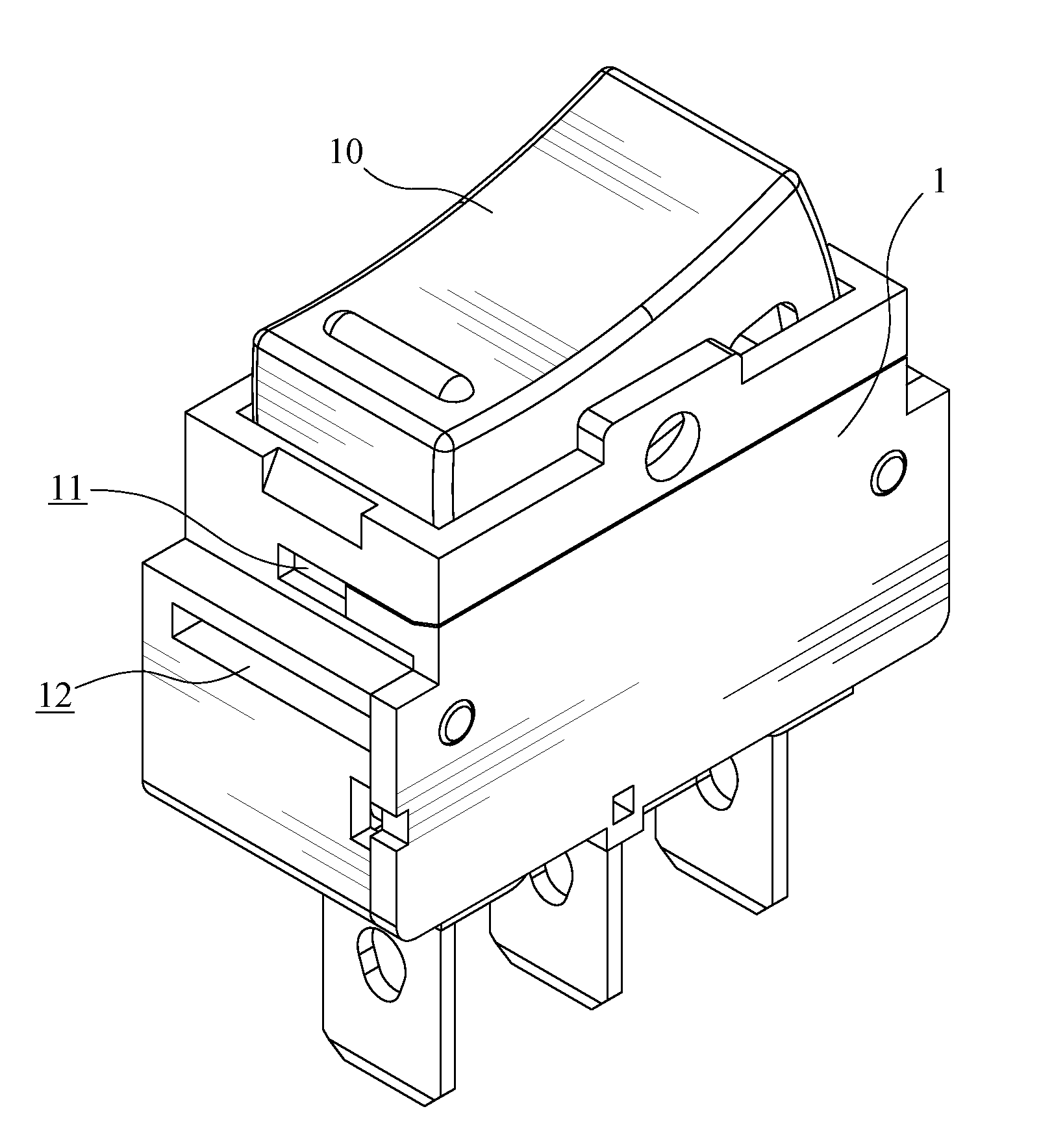
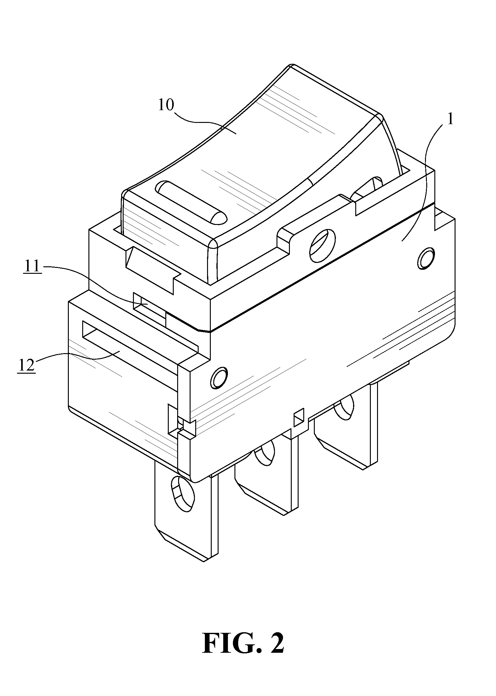
[0016]Referring to FIGS. 2 to 4, a switch assembly according to an embodiment of the present invention includes a switch casing 1 and a button 10 pivotally connected with the switch casing 1. The switch casing 1 includes at least two sets of fastener slots 11 and 12. A set of first fastener slots 11 are disposed at two sides of the switch casing 1, respectively. A set of second fastener slots 12 are disposed at two sides of the switch casing 1, respectively. The first fastener slots 11 are located above the second fastener slot 12.

[0017]Referring to FIG. 3, the button 10 is pivotally connected with the switch casing 1 to turn the circuit to “ON” or “OFF” states. A cover plate 2 has a set of hooks 21 corresponding to the first fastener slots 11 and the second fastener slots 12 of the switch casing 1. The hooks 21 are extended from a lower surface of the cover plate 2 and respectively disposed at two sides of an opening 20. The hooks 21 are engaged with the first fastener slots 11 or ...


PUM


Abstract

A switch assembly includes a switch casing and a button pivotally connected with the switch casing. The switch casing has at least two sets of fastener slots disposed at two sides of the switch casing, respectively. The cover plate has a set of hooks corresponding to the fastener slots. The hooks are engaged with either set of the fastener slots. In addition, an upper side of the switch casing where the button is pivotally connected includes at least one positioning protrusion that is correspondingly engaged with a positioning groove provided on the cover plate to prevent erroneous assembly of the cover plate with the switch casing.

Description

BACKGROUND OF THE INVENTION[0001]1. Field of the Invention[0002]The present invention relates to a switch assembly, and more particularly to a switch assembly having a switch casing that has at least two sets of fastener slots disposed at two sides of the switch casing to engage with a set of hooks of a cover plate.[0003]2. The Prior Arts[0004]Many switch assembly are currently available in the market. As shown in FIG. 1, a conventional switch assembly includes a switch casing 100, a button 101 disposed at an upper side of the switch casing 100, an extending edge 102 provided at a periphery of the button 101, and two resilient fasteners 103 respectively disposed at two sides of the switch casing 100. When the switch casing 100 is assembled with a cover plate 104, the switch casing 100 is inserted into an opening 105 from an upper side of the cover plate 104. The switch casing is disposed below the cover plate 104 and the button 101 is exposed out of the cover plate 104. The fastener...

Claims


Application Information

Patent Timeline
Patent Type & Authority Applications(United States)
IPC IPC(8): H01H21/04
CPCH01H23/04
Inventor YU, TSUNG-MOU
Owner YU TSUNG MOU
Why Eureka
Try Eureka