Torque Transmission Device With Electrical Insulation

a transmission device and transmission device technology, applied in the direction of fluid couplings, gearings, engine starters, etc., can solve the problems of affecting the operation, affecting the transmission, and affecting the transmission, so as to prevent the transmission of current particularly effectively

Inactive Publication Date: 2013-05-23
ZF FRIEDRICHSHAFEN AG
View PDF10 Cites 8 Cited by
  • Summary
  • Abstract
  • Description
  • Claims
  • Application Information

AI Technical Summary

Benefits of technology

[0010]According to a preferred embodiment, the insulation element is made from an electrically insulating material, particularly plastic or ceramic. Apart from good insulating properties, ceramic also has the advantage that it withstands high mechanical loads. Plastic, on the other hand, is advantageous because it can deform easily.
[0030]According to another advantageous embodiment, the insulation element is arranged between a thrust washer and a bearing washer of the thrust bearing support. Optional advantageous elements for preventing misassembly and / or elements for securing against rotation can be formed so as to act in direction of the thrust washer and in direction of the bearing washer.

Problems solved by technology

The current introduced into the transmission in this way can result in damage to transmission components and impaired operation.
For example, it can lead to fusing of movable parts due to the heating action of the current.
However, it is a drawback of this prior art that the electrical insulating effect, particularly in the case of the coating, is designed merely for the welding process.
During continuous introduction of current via the starter and the movement of the springs at the coating, the coating can be damaged and only provides an insufficient current insulation.
Also, forming the spring pockets as plastic element provides only an insufficient electrical insulation because precisely during high mechanical stresses, plastic elements at the spring seats do not withstand the mechanical stresses.
Moreover, it has been shown that arranging plastic elements in the spring pockets impedes the assembly of the torsion damper and adds significantly to cost because of the additional time.

Method used


Image

  • Torque Transmission Device With Electrical Insulation
  • Torque Transmission Device With Electrical Insulation
  • Torque Transmission Device With Electrical Insulation

Examples


Embodiment Construction

[0052]In the following similar elements or similarly functioning elements are designated by the same reference numerals.

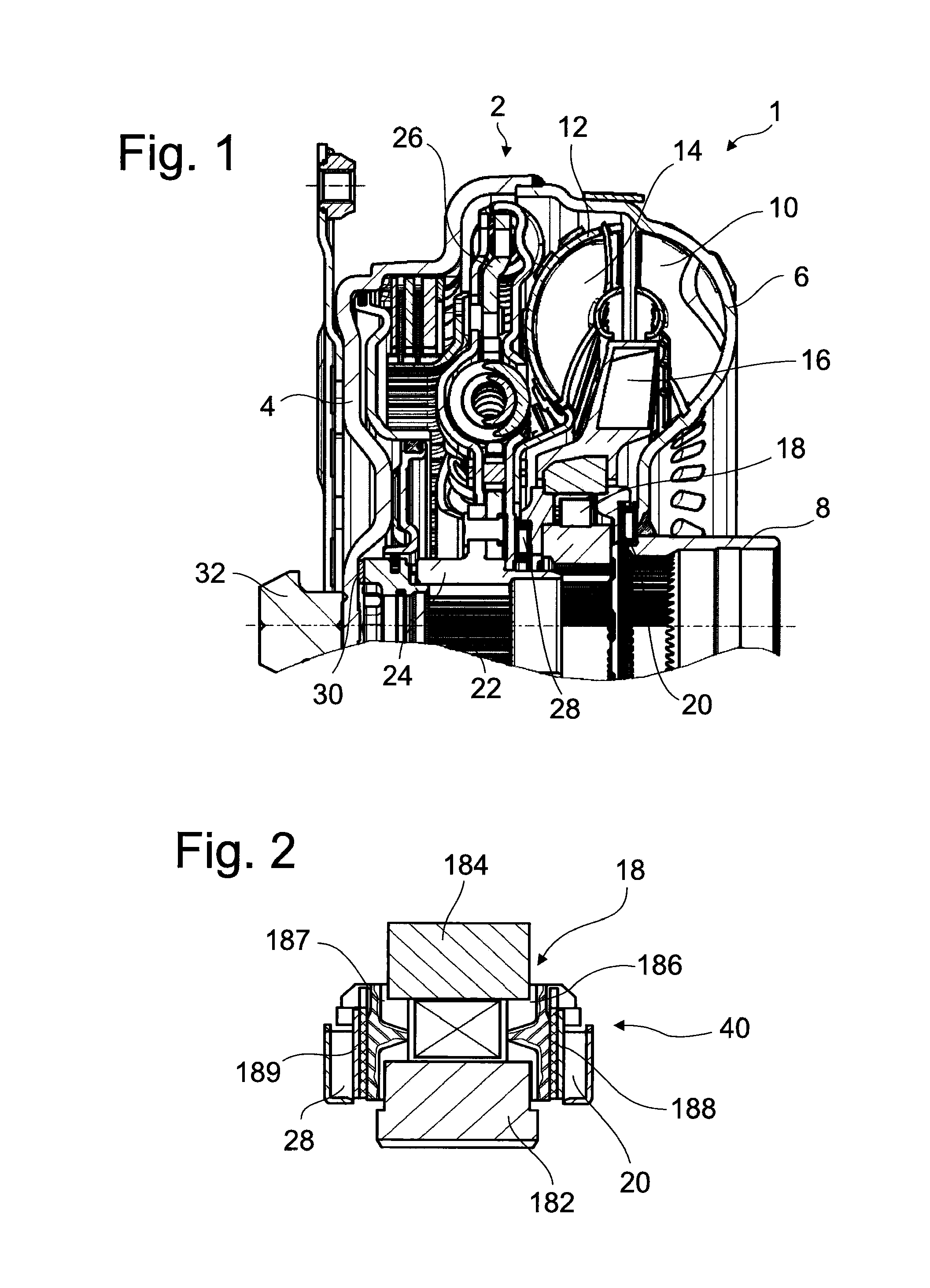
[0053]FIG. 1 shows a wet clutch arrangement 1 in the form of a hydrodynamic torque converter. The housing 2 has at its side facing a drive (not shown) a housing cover 4 which is fixedly connected to an impeller shell 6. This impeller shell 6 merges with an impeller hub 8 in the radially inner region.

[0054]The impeller shell 6 together with impeller blades forms an impeller 10 which cooperates with a turbine 14 having a turbine shell 12 with turbine blades and with a stator 16 having stator blades. Impeller 10, turbine 14 and stator 16 form a hydrodynamic circuit in a known manner.

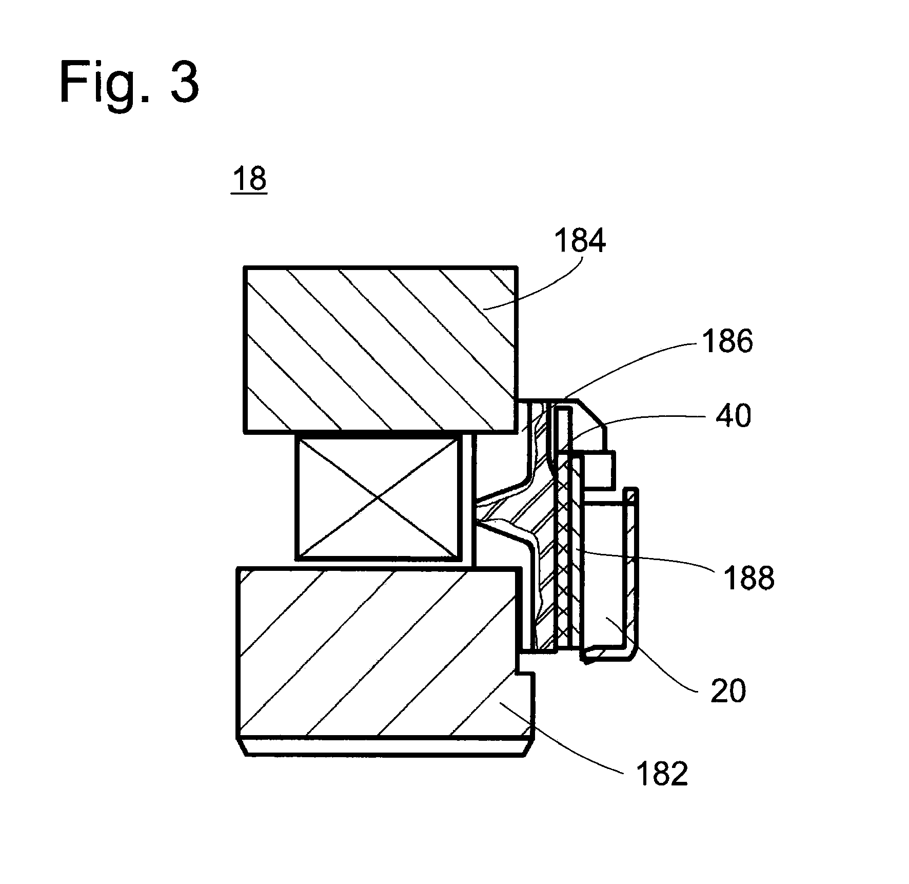
[0055]The stator 16 is arranged on a freewheel 18 which is supported axially at the impeller hub 8 by a thrust bearing support 20. The impeller hub 8 is hollow and receives a transmission input shaft 22 within its interior.

[0056]By means of toothing, the transmission input shaft 22 receive...


PUM


Abstract

A torque transmission device, particularly for a motor vehicle, for the transmission of a torque from a driving unit, particularly from an internal combustion engine, to a driven unit, particularly a transmission, has at least one bearing location which has at least one bearing support acting in axial and / or radial direction, wherein an insulation element preventing a flow of electric current is provided in the region of the at least one bearing location.

Description

BACKGROUND OF THE INVENTION[0001]1. Field of the Invention[0002]The present invention is directed to a torque transmission device, particularly for a motor vehicle, for the transmission of a torque from a driving unit, particularly from an internal combustion engine, to a driven unit, particularly a transmission, having at least one bearing location which has at least one bearing support acting in axial and / or radial direction.[0003]2. Description of the Related Art[0004]A torque transmission device of the type mentioned above can be, for example, a clutch arrangement, a dual-mass flywheel or a torque converter. Torque transmission devices of this kind are commonly arranged in the drivetrain of a vehicle between a driving unit, i.e., the engine, and a driven unit, i.e., the transmission. However, in modern drivetrains it has been shown that while most of the current can still be diverted to the body via a ground cable during the process of starting the vehicle by means of a starter,...

Claims


Application Information

Patent Timeline
Patent Type & Authority Applications(United States)
IPC IPC(8): F16C33/02F16C33/30
CPCF16C33/02F16C33/30F16C19/52F16C41/00F16H57/021F16C2202/30F02N11/08F16H41/24F16C17/24F16C17/04F16C19/30F16D41/06
Inventor FREY, PETERHEULER, MICHAELMENCHER, GEORG
Owner ZF FRIEDRICHSHAFEN AG
Why Eureka
Try Eureka