Eureka AIR delivers breakthrough ideas for toughest innovation challenges, trusted by R&D personnel around the world.

Control apparatus for automobile

a technology for controlling apparatus and automobiles, applied in the direction of electric controllers, ignition automatic control, instruments, etc., can solve the problems of inefficiency and the inability to adopt software between specifications, and achieve the effect of reducing labor and time for software development, reducing the risk of erroneous assembly or the like, and reducing the risk of programming glitches or the lik

Active Publication Date: 2006-08-03
DENSO CORP
View PDF24 Cites 8 Cited by
  • Summary
  • Abstract
  • Description
  • Claims
  • Application Information

AI Technical Summary

Benefits of technology

[0009] The present invention has an object of providing a control apparatus for an automobile which can achieve sharing of control software between electronic devices even in a case that an arrangement of terminal pins of an ECU which the control software of the electronic device designates for input / output differs depending on the specification of the automobile, and at the same time prevent erroneous assembly on the electronic devices.
[0011] In the present invention, in response to the specification of a controlled electronic device, the rearrangement table in accordance with the specification may be written into and stored in an electrically rewritable ROM (for example, EEPROM or flash ROM) as needed. In this way, a change of the contents of the designation terminal pins for the same software due to a specification alternation or the like of the automobile or an additional mounting of a controlled electronic device can be easily made by writing the necessary rearrangement table into the ECU as needed. It is noted that the control software described by using terminal pin variables may be stored in a mask ROM as a fixed storage section if the capacity thereof is relatively small, and may be stored in an electrically rewritable ROM as a flash ROM if the capacity thereof is relatively large.
[0012] Next, the content of the rearrangement table may be defined so that a function provided to an electronic device by the control software differs from one another depending on a mounting position of the same electronic device to the automobile. In this way, the terminal pin connected to the electronic device may be changed in response to a mounting position of the electronic device to the automobile and also the control software may be shared by using the terminal pin variable, thus providing efficient assembly.
[0014] A risk of erroneous assembly or the like can be reduced by fixedly positioning the terminal pins of the ECU connected to the controlled electronic device in response to the mounting position to the automobile. On the other hand, since the function required for the electronic device in each mounting position differs depending on the automobile specification, a plurality of control software for each function have to be normally provided for each terminal pin fixed in each mounting position of the electronic device.
[0015] According to the above arrangement, however, when the control software of each function is provided with only one pattern by using a terminal pin variable, it is not necessary to prepare the plurality of the control software for each function simply by replacing the rearrangement table defining the terminal pin distributed to each control software, depending on the automobile specification. As a result, it is possible to reduce labor and time for software development and also a risk of programming glitches or the like.

Problems solved by technology

This, however, raises the following problems.
However, the situation where in an assembly line of the same kind of automobiles, terminal pins of the ECU connected to the electronic device located at the same position inside the automobile frequently change depending on the automobile specification is not practical also from a viewpoint of the problem with possible erroneous assembly.
Therefore, the sharing of the software between the specifications has not been adopted yet.
In this case, it is required to provide the software in which the designation of the terminal pins as the input / output points of the automobile is variably changed with each specification, thus raising the problem of inefficiency.

Method used


Image

  • Control apparatus for automobile
  • Control apparatus for automobile
  • Control apparatus for automobile

Examples


Embodiment Construction

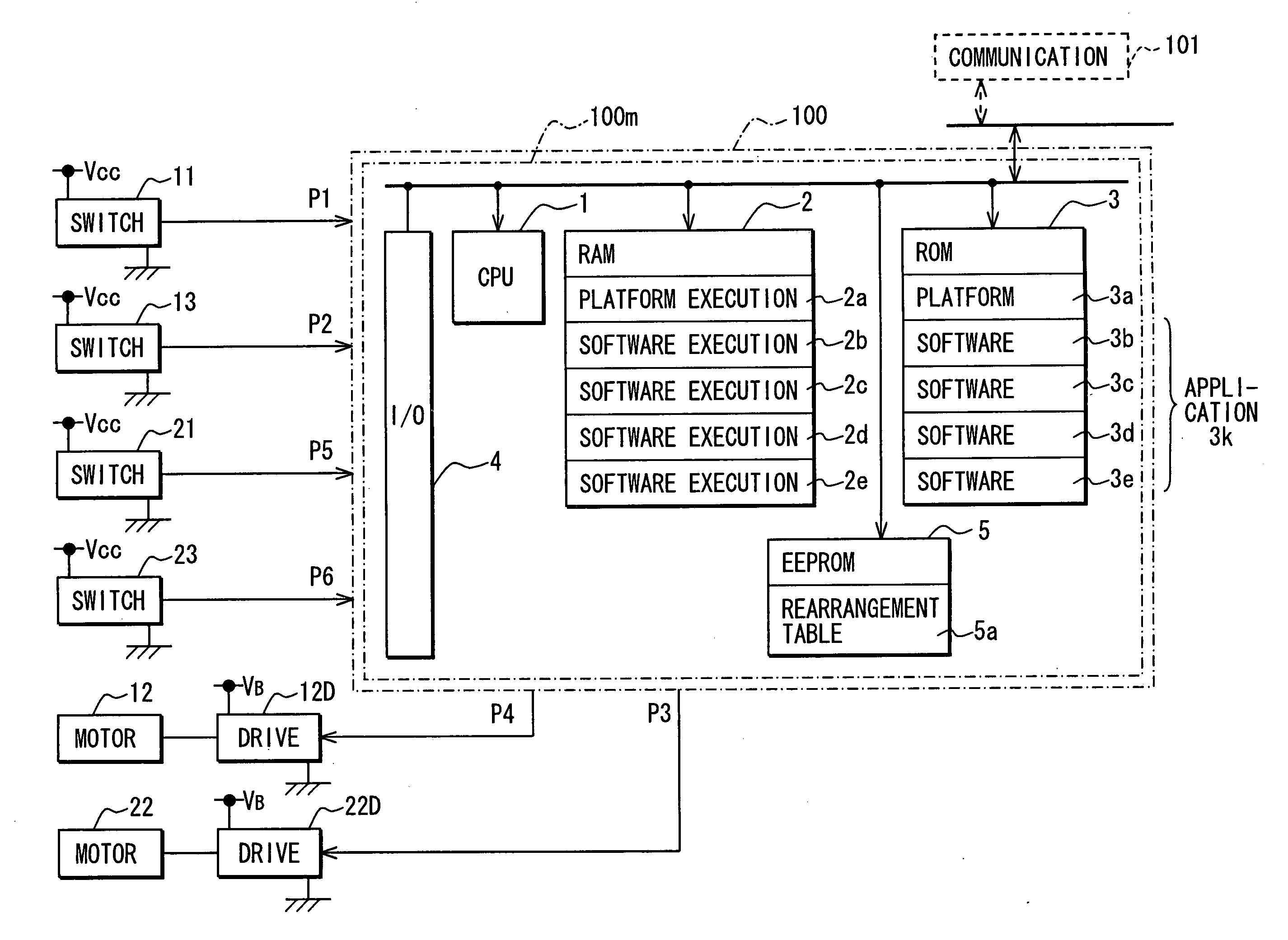
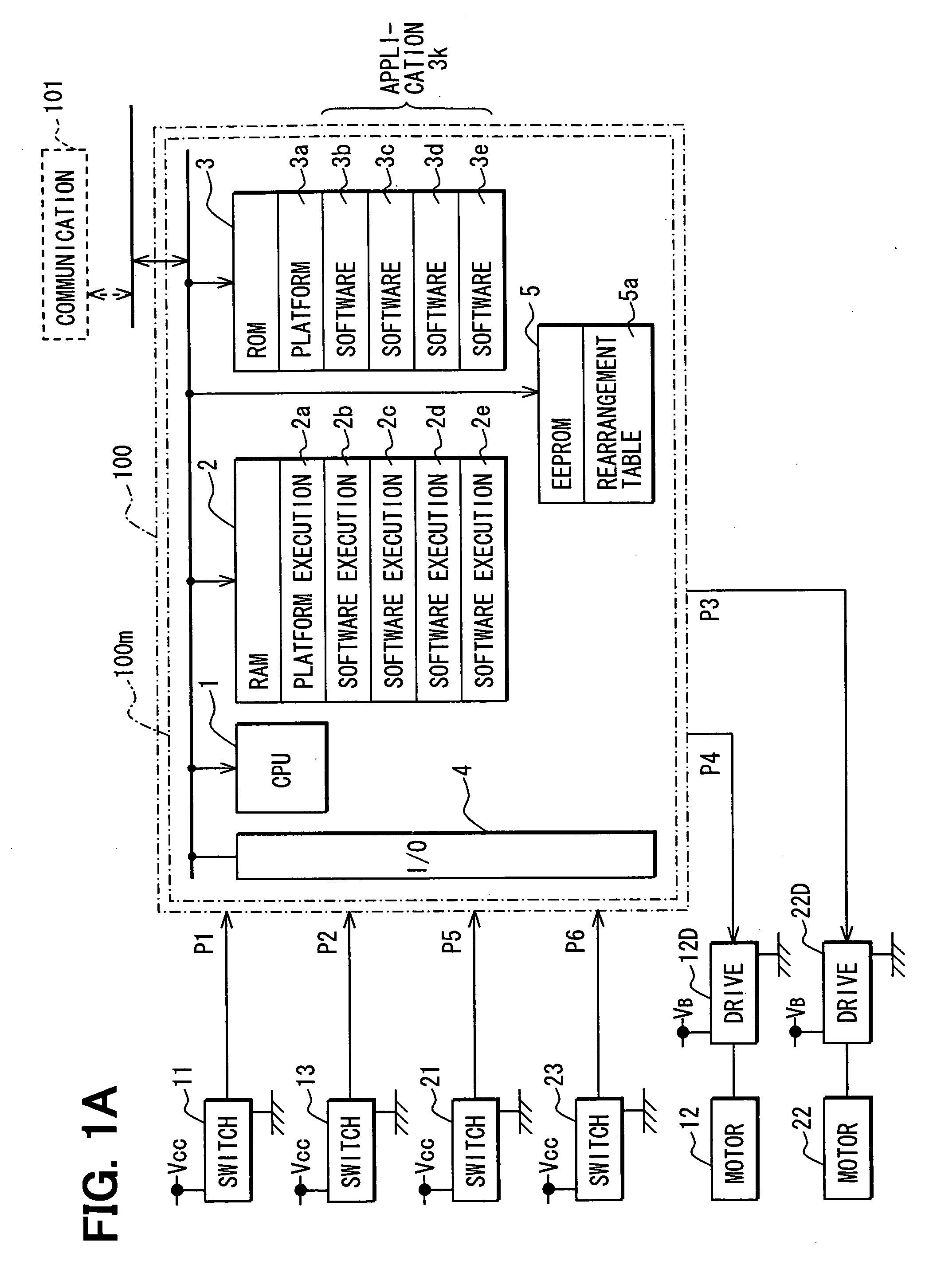
[0040] Referring to FIG. 1A, an electronic control unit (ECU) 100 is constructed mainly of a microprocessor 100m in which a CPU 1, a RAM 2, a ROM 3, an EEPROM 5 (including a flash ROM) and an input / output port 4 (I / O port) are connected over buses.

[0041] The ROM 3 and the EEPROM 5 constitute a fixed storage section. The ECU 100 is for a chassis system, which performs control of the chassis system for an automobile in the preferred embodiment. The ROM 3 is provided with a platform 3a and control software 3b to 3e for performing a variety of chassis system functions. A rearrangement table 5a is separated from the software 3b to 3e and is stored in the EEPROM 5.

[0042] The platform serves to provide an operating environment in common with each application even in a case hardware as a base differ among each application and is constructed to include basic software to each application and further, an interface program providing a link with the applications or the hardware. A detailed exp...


PUM


Abstract

In a control apparatus for an automobile with a microcomputer, the control software stores the type of the terminal pin allocated to each control function in the fixed storage section, in a non-fixed state by using a terminal pin variable, in order to alter an allocation arrangement of the terminal pin to the control function. A rearrangement table showing the allocation arrangement of the terminal pin to the control function is stored in a rearrangement table storage section. An allocation content of the terminal pin to each control function is read out from the rearrangement table memory section and specific information of a corresponding terminal pin is substituted into the terminal pin variable corresponding to the each control function included in the control software, based upon the allocation content.

Description

CROSS REFERENCE TO RELATED APPLICATION [0001] This application is based upon and incorporates herein by reference Japanese Patent Application No. 2005-26928 filed on Feb. 2, 2005. FIELD OF THE INVENTION [0002] The present invention relates to a control apparatus for an automobile. BCKGROUND OF THE INVENTION [0003] Recently, control of an electronic device mounted in an automobile is performed by using a hardware unit including a microcomputer called an electronic control unit (ECU) as disclosed in U.S. Pat. No. 6,898,500B2 (JP 2004-122803A). Also in many cases a single ECU performs control of a plurality of electronic devices. In this case, input / output of a signal to the ECU is made via a terminal pin (for example, a terminal pin disposed for mounting the ECU as a hardware unit to a socket in a side of the automobile), and an input terminal pin and an output terminal pin are individually allocated to each electronic device. [0004] However, even in the same type of automobiles, the ...

Claims


Application Information

Patent Timeline
IPC IPC(8): G05D1/00
CPCG06F15/7814
Inventor HANZAWA, KIICHIRO
Owner DENSO CORP
Why Eureka
Eureka Blog
Learn More