Roller chain

A technology of chains and rollers, applied in the direction of transmission chains, etc., can solve the problems of power transmission friction loss, large contact area, and large friction resistance, and achieve the effects of reducing friction loss, reducing contact area, and reducing weight

Inactive Publication Date: 2007-04-18
TSUBAKIMOTO CHAIN CO
View PDF1 Cites 9 Cited by
  • Summary
  • Abstract
  • Description
  • Claims
  • Application Information

AI Technical Summary

Problems solved by technology

[0007] When the roller chain 31 contacts guide components such as the tension rod G1 and the guide rod G2, as mentioned above, if the back surfaces of the outer link plate 32 and the inner link plate 35 are at the same height, since the two contact the guide components and have a large contact area , the friction resistance is large, so there is a problem of friction loss during power transmission
In particular, when the roller chain 31 is assembled into an automobile engine and used as a timing chain, if the friction loss is large, there is a problem of high fuel consumption.

Method used


Image

  • Roller chain
  • Roller chain
  • Roller chain

Examples


Embodiment Construction

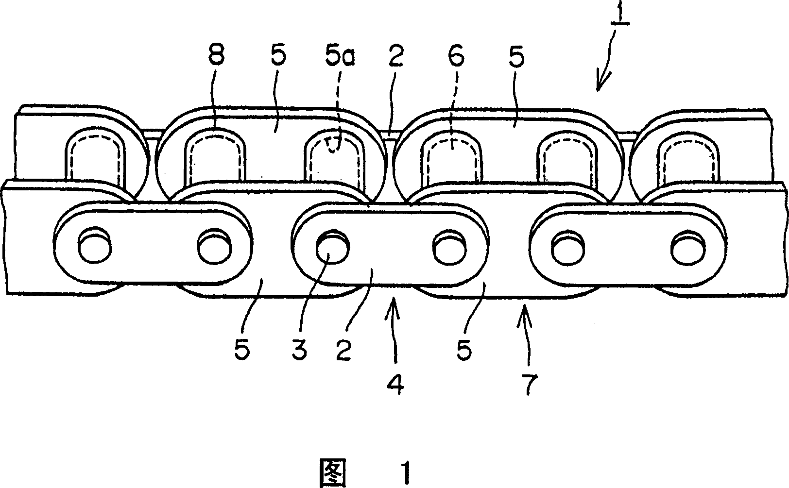
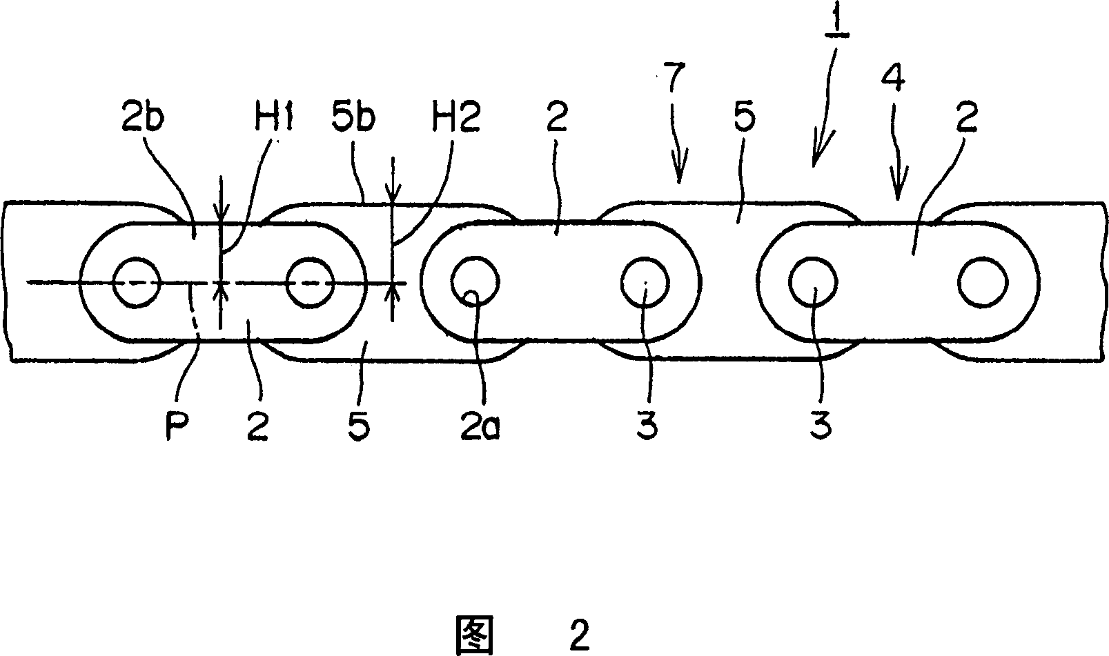
[0044] Embodiment 1 of the present invention will be described with reference to FIG. 1 and FIG. 2 . FIGS. 1 and 2 are partial perspective views and partial side views showing a roller chain exaggeratedly showing a roller chain in which the rear surface height of the outer link plate is lower than that of the inner link plate.

[0045] The roller chain 1 includes: the outer link 4 with the pin 3 embedded and fixed in the pin hole 2a of a pair of outer link plates 2; and the sleeve with the sleeve 6 embedded and fixed in the pair of inner link plates 5 The inner link 7 and the roller 8 in the hole 5a are loosely inserted into the bush 6 so as to be rotatable. Further, the roller chain 1 is formed to be bendable by loosely inserting the pins 3 into the bushes 6 to alternately connect the outer links 4 and the inner links 7 .

[0046] In the roller chain 1, the outer link plate 2 of the outer link 4 and the inner link plate 5 of the inner link 7 all form an ellipse. In addition...


PUM


Abstract

A roller chain, in which when the roller chain comes into contact with guide members, the contact area is reduced, so that frictional resistance is decreased and friction loss generated during transmission of power is reduced. A roller chain is formed such that an outer link assembly comprising a pair of outer link plates and an inner link assembly comprising a pair of inner link plates are alternately connected along the pitch line of the chain to each other by pins. The distance from the pitch line of the roller chain to outermost edge surfaces of the link plates is the backside height. The backside height of the outer link plates is lower than the backside height of the inner link plates. When the roller chain contacts and slides on the guide members, the outer link plate does not come into contact with the guide members so that friction loss can be reduced. In some embodiments, some of the link plates are concave ellipsoidal (gourd-shaped) and others are non-concave ellipsoidal (cucumber-shaped).

Description

technical field [0001] The present invention relates to a roller chain used in a timing transmission system of an internal combustion engine such as an automobile engine, and in particular to a roller chain capable of reducing friction loss caused by sliding friction with guide components such as tension rods and guide rods. Background technique [0002] In recent years, as a part of the timing transmission system of the automobile engine, due to the requirements of high load, high speed and no maintenance, roller chains are used to replace the toothed transmission belts that have been widely used in the past. (Refer to Patent Document 1.). [0003] When the roller chain is used in a timing transmission system of an automobile engine, as shown in FIG. 5, the timing chain Tc is wound around the crank sprocket S1 and the cam sprockets S2, S2. The timing chain Tc is in sliding contact with guide members such as the tension rod G1 and the guide rod G2 to which appropriate tensi...

Claims


Application Information

Patent Timeline
Patent Type & Authority Applications(China)
IPC IPC(8): F16G13/06
CPCF16G13/06
Inventor 永尾宪一
Owner TSUBAKIMOTO CHAIN CO
Why Eureka
Try Eureka