Drilling device with a controller for the feeding unit

a technology of feeding unit and drilling device, which is applied in the direction of work benches, metal-working machine components, manufacturing tools, etc., can solve the problems of permanent damage, inability to know the feeding unit, and inability to properly shape the drilling, etc., and achieve the effect of convenient mounting/dismounting of the apparatus

Active Publication Date: 2013-02-14
HUSQVARNA AB
View PDF5 Cites 10 Cited by
  • Summary
  • Abstract
  • Description
  • Claims
  • Application Information

AI Technical Summary

Benefits of technology

[0007]In view of the above, it is an objective to solve or at least reduce the problems discussed above. In particular, an objective is to provide methods and systems for feeding the drill of the drilling machine into the drilling object and be able to sense the load conditions, vary the feeding force and to provide easy mounting / dismounting apparatus.

Problems solved by technology

Here, the drill may enter the drilling object with a predetermined speed and force set by the user, however, the drilling head might slide away from the desired area on the drilling object and the drilling may not yield a proper shape.
This may lead to the motor being overloaded and may cause permanent damage to it.
Another problem of the system is that the feeding unit may not know that the drilling operation is complete and it may continue to feed.
This may cause damage to other peripheral systems and unnecessary loss of electric power.
Also, mounting and dismounting of the current feeding systems is a tedious process as flywheel clutches are used, which may complicate the whole process.
Also, use of screws and other such securing components, may make the process time-consuming.

Method used


Image

  • Drilling device with a controller for the feeding unit
  • Drilling device with a controller for the feeding unit
  • Drilling device with a controller for the feeding unit

Examples


Embodiment Construction

[0058]The present invention will be described more fully hereinafter with reference to the accompanying drawings, in which example embodiments of the invention incorporating one or more aspects of the present invention are shown. This invention may, however, be embodied in many different forms and should not be construed as limited to the embodiments set forth herein; rather, these embodiments are provided so that this disclosure will be thorough and complete, and will fully convey the scope of the invention to those skilled in the art. For example, one or more aspects of the present invention can be utilized in other embodiments and even other types of devices. In the drawings, like numbers refer to like element.

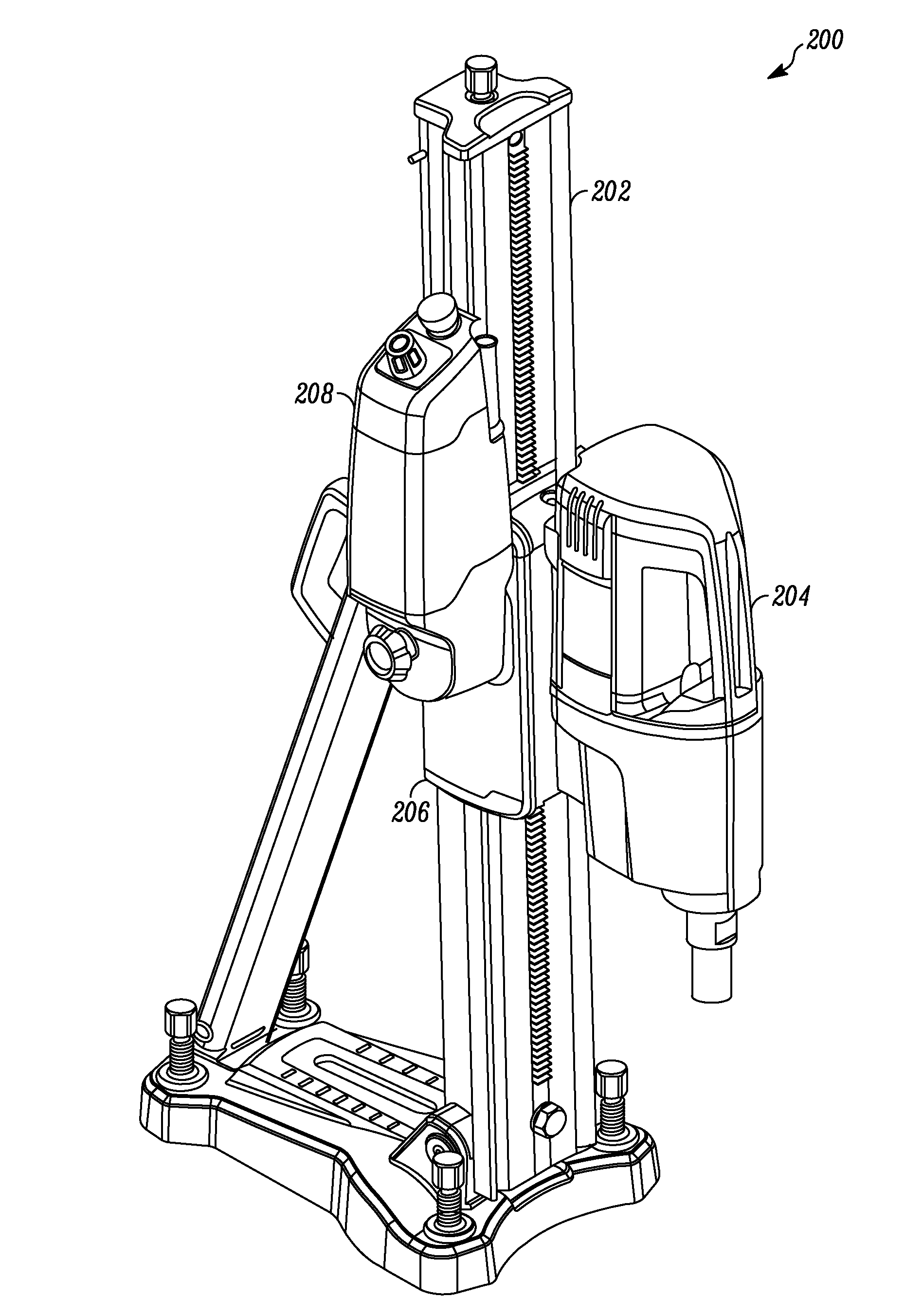
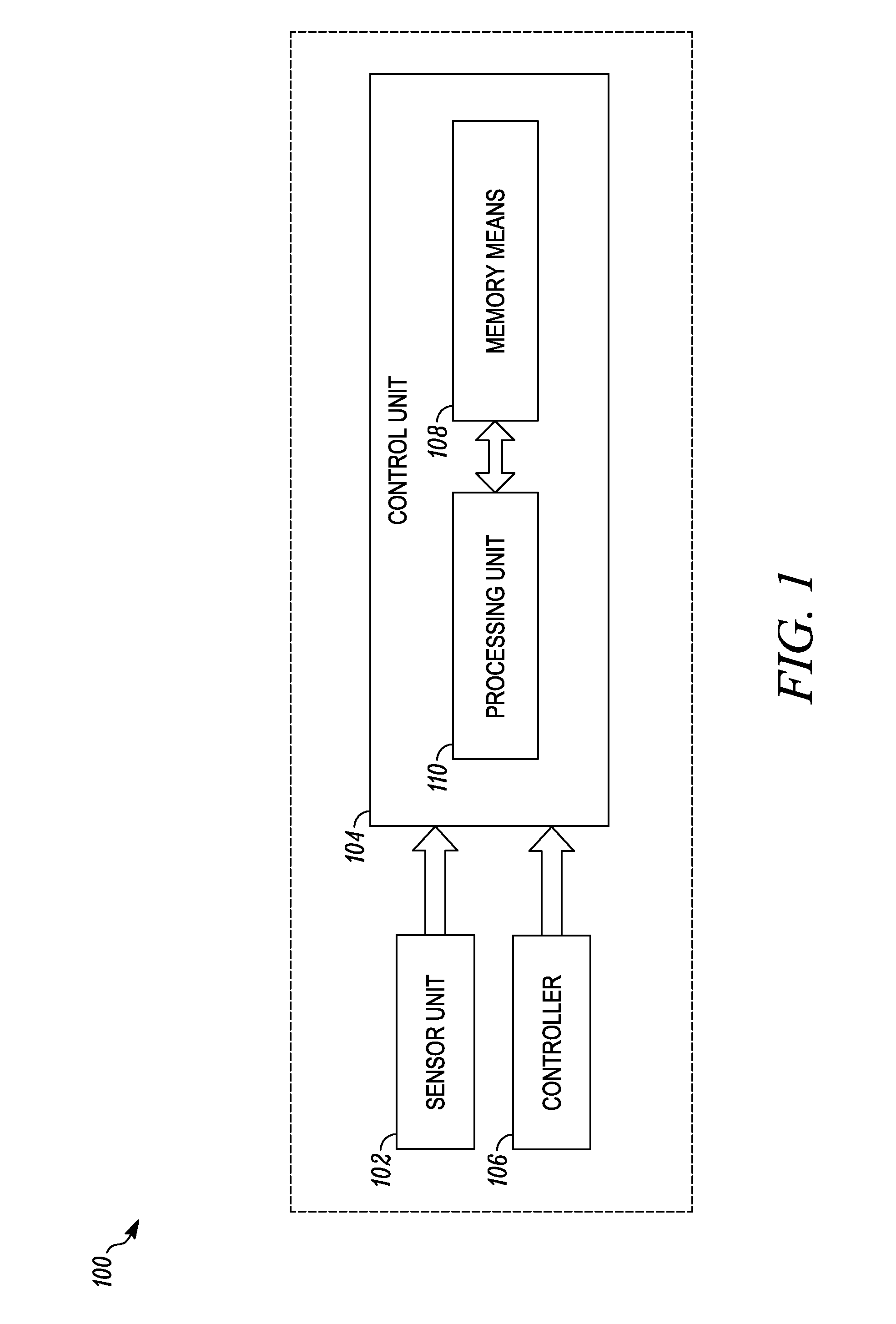
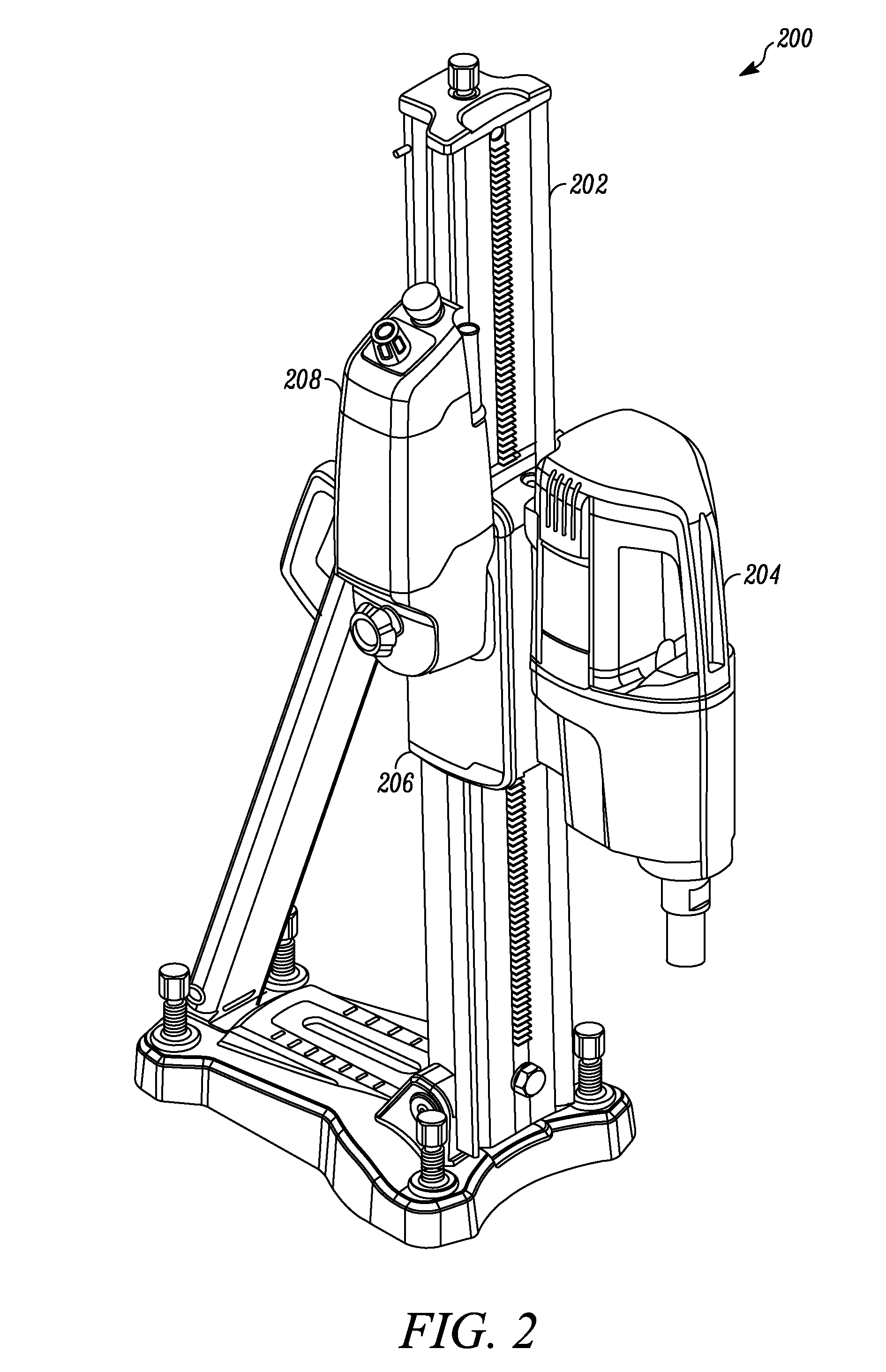
[0059]FIG. 1 illustrates a block diagram of a system 100, according to an embodiment of the present invention. In an embodiment of the present invention, the system 100 may be embodied in a feeding unit for controlling the feed of a drill into a drilling object.

[0060]In an ...


PUM

PropertyMeasurementUnit
angleaaaaaaaaaa
speedaaaaaaaaaa
electric currentaaaaaaaaaa

Abstract

The present invention relates to methods and systems for automatically feeding a feeding housing (206) of a drilling device (200). The drilling device (200) includes a drill stand (202), a drilling machine (204) and a feeding housing (206). Further, the drilling machine (204), which is suspended by the feeding housing (206), includes a drill with a drilling motor for performing a drilling operation through a drilling object. The feeding unit (208) includes an electric feeding motor for feeding the feeding housing (206) along the stand (202). Further, the feeding unit (208) also includes a controller for manually influencing the feeding motor's direction of rotation, speed and feeding force.

Description

TECHNICAL FIELD[0001]The present invention relates to an auto-feeding system. In particular, the present invention relates to methods and devices for automatically controlling the feeding operation of a drilling machine or the like.BACKGROUND[0002]Feeding units may be used for feeding any machine, such as a drilling machine, boring machine and the like, into a target object. Also, when the target object is large, the feeding is particularly helpful as a human operator might not be needed to supervise the operation. This may also be helpful in areas where it is not possible for the human operator to access and supervise the drilling operation.[0003]There are many systems known in the art that implement the feeding unit. In such systems, the feeding motor may feed drilling heads along the stand at a constant feeding force. Here, the drill may enter the drilling object with a predetermined speed and force set by the user, however, the drilling head might slide away from the desired are...

Claims


Application Information

Patent Timeline
Patent Type & Authority Applications(United States)
IPC IPC(8): B23B47/20B23B47/00
CPCB23Q5/36B25H1/0064Y10T408/17Y10T408/16Y10T408/5647Y10T408/6771Y10T408/675
Inventor JONSSON, ANDREASJOHANSSON, ROBERT
Owner HUSQVARNA AB
Why Eureka
Try Eureka