Connector

a technology of connecting rods and connectors, applied in the direction of multiple conductor connectors, printed circuit non-printed electric components association, coupling device connection, etc., can solve the problems of high voltage affecting the operation of electronic components, risk in the continuing use of such switches, etc., and achieve the effect of safe supply of electric power and higher voltag

Inactive Publication Date: 2013-02-14
FUJITSU COMPONENENT LTD
View PDF3 Cites 5 Cited by
  • Summary
  • Abstract
  • Description
  • Claims
  • Application Information

AI Technical Summary

Benefits of technology

[0014]According to at least one embodiment, a connector for use with a direct-current power supply or a power supply

Problems solved by technology

Concerning the electric power that is supplied to electric equipment, there may be a case in which high voltage affects a human body and the operation of electronic components.
When power supplied from a power sup

Method used


Image

  • Connector
  • Connector
  • Connector

Examples


first embodiment

[0046]

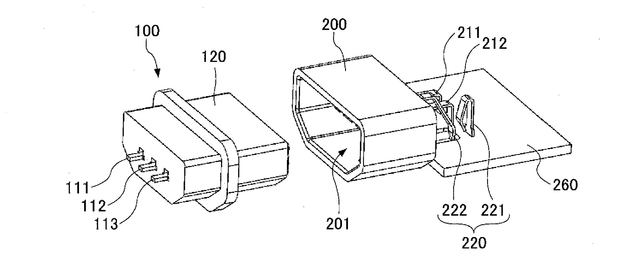
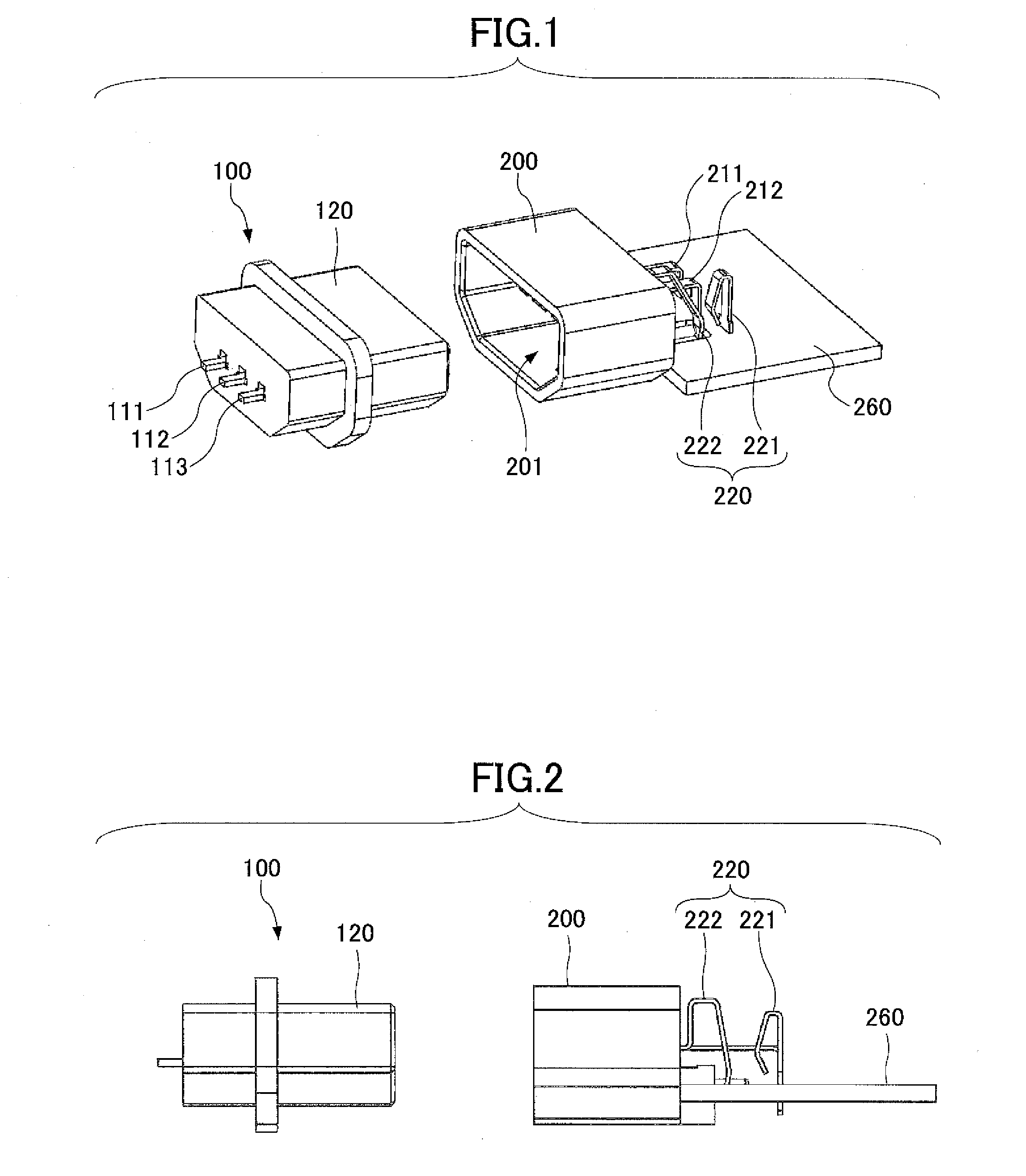
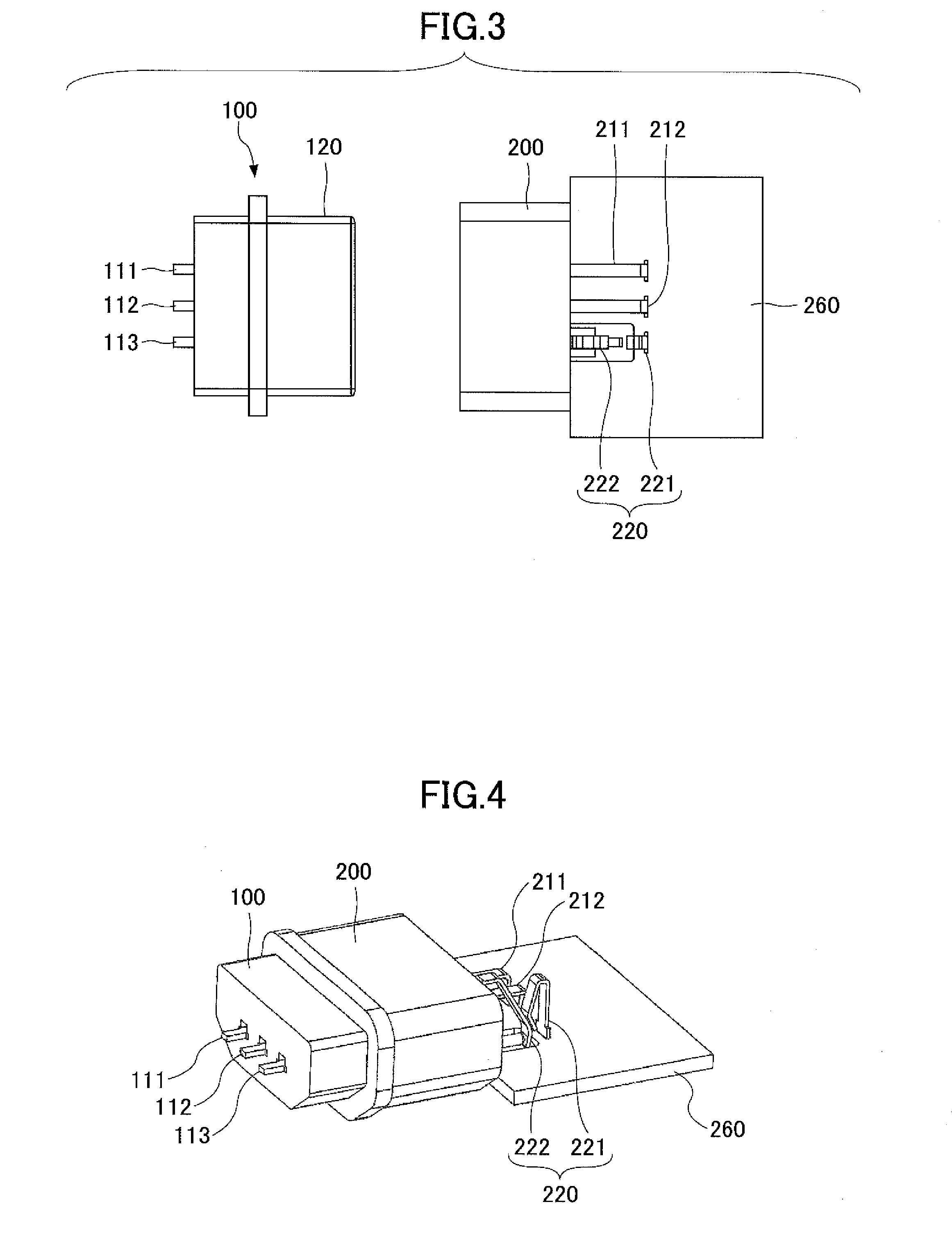
[0047]In the following, a description will be given of the structure of a connector according to a first embodiment. The connector of the present embodiment includes a plug connector 100 and a jack connector 200 illustrated in FIG. 1 through FIG. 3.

[0048]The plug connector 100 has a case part thereof formed of an insulating material, and has three plug-electrode terminals 111, 112, and 113 formed of an electrically conductive material such as metal. The plug-electrode terminals 111, 112, and 113 may be connected to a power-supply cable (not shown). The plug connector 100 has a plug connector coupling part 120 thereof, which is inserted into the interior space of the jack connector 200 for fitting connection. The plug-electrode terminals 111, 112, and 113 are formed to project from the opposite side of the plug connector 100 to the plug connector coupling part 120. In the description of the present embodiment, the plug-electrode terminal 111 may be connected to the plus of the ...

second embodiment

[0069]In the following, a second embodiment will be described. In this embodiment, as illustrated in FIG. 28, the switch part 220 having the fixed part 221 and the movable part 222 is provided for connection with the plug-electrode terminal 113, and, also, the switch part 222 having the fixed part 226 and the movable part 227 is provided for connection with plug-electrode terminal 111. With this arrangement, the control of on-or-off state of power supply can be performed substantially simultaneously between the plus side and the minus side.

[0070]In this case, as illustrated in FIG. 29, a single movable member 240a that can push the movable part 222 of the switch part 220 and the movable part 227 of the switch part 225 at the same time may be employed. This arrangement reduces the number of components, thereby achieving cost reduction.

[0071]Configurations other than those described above are the same as or similar to those of the first embodiment.


PUM


Abstract

A connector includes a first connector and a second connector configured to engage with the first connector to establish electrical connection, wherein the first connector includes a first contact terminal, and the second connector includes: a second contact terminal configured to come in contact with the first contact terminal; a switch part connected to the second contact terminal and including a fixed part and a movable part; and a movable member capable of pushing the movable part toward the fixed part, wherein the movable member is pushed by the first connector when the first connector engages with the second connector, and the movable member pushes the movable part toward the fixed part to bring the movable part in contact with the fixed part.

Description

BACKGROUND OF THE INVENTION[0001]1. Field of the Invention[0002]The disclosures herein relate to a connector.[0003]2. Description of the Related Art[0004]Electrical equipment generally operates with electric power supplied from a power supply.[0005]For the purpose of supplying electric power, connectors are typically used to supply electric power from the power supply to the electric equipment. Such connectors include a male-type connector having one or more male pins and a female-type connector having one or more female sockets, which mate with each other to establish electrical connection, as disclosed in Patent Documents 1 and 2.[0006]In recent years, the supply of a direct-current high-voltage electric power has been under study for local-area electric power transmission as a measure against global warming. With such a power supply arrangement, power loss is small at the time of voltage conversion and electric power transmission, and, also, there is no need to use thick cables. ...

Claims


Application Information

Patent Timeline
IPC IPC(8): H01R24/68H01R4/48H01R4/28
CPCH01R2103/00H01R13/6278H01R13/7033H05K2201/10446H05K1/18H05K2201/10189H01R24/62
Inventor BEAK, SEUNGSEOKKIRYU, KOICHIYUBA, TAKASHIIWAMOTO, DAIEINAKAMURA, AKIO
Owner FUJITSU COMPONENENT LTD
Why Eureka
Try Eureka