Lumbar support seat

Inactive Publication Date: 2013-02-21
YOON WOOK
14 Cites 18 Cited by

AI-Extracted Technical Summary

Problems solved by technology

Furthermore, the user may easily sit with his legs crossed, the weight of the upper body that is applied to the hipbone becomes unbalanced, possibly causing the deformation of skeleton.
If a user seats on a chair via the auxiliary chair (a), his legs become spread such that crossing his legs becomes difficult, the pelvis portion becomes bent forwards, and the lumbar vetebra portion is induced to be naturally bent.
The prior art auxiliary chair a has, howe...

Method used

[0046]Even though the lumbar support seat M according to the present invention as constructed above is intended to be placed on the floor, a chair or sofa, it may be independently used as a chair by preparing the seat main body 100 and the lumbar supporting die 200 with sufficient strength and mounting supporting legs to the lower end of the seat main body 100.
[0049]Further, as the both buttock portions of the user push the both side edges of the concave seat main body 100, the rear portion of the seat main body 100 and the lumbar supporting die 200 provided thereto naturally push the lumbar vertebra portion and the spine so that the lumbar vertebra portion and the pelvis portion may be stably supported. Therefore, the lumbar vertebra portion is not applied with an excessive load in spite of long time sitting and the lumbar vertebra portion may be prevented from the damage or pain.
[0051]In the meantime, in the lumbar support seat M of the present invention, the upper surface of the seat main body 100 and the front surface of the supporting plate 230 are respectively provided with the air cushions 120 and 240, promoting the sitting comfort.
[0052]Furthermore, each of the air cushions 120 and 240 is divided into the left cushion section 120a, 240a and the right cushion section 120b, 240b, which are connected to each other via the small-diamet...

Benefits of technology

[0020]According to the lumbar support seat according to the present invention as described above, the seat main body has the upper central portion, which is curvedly indented so as to correspond to the shape of pelvis portion, so that the rear portion of the seat main body and the lumbar supporting die provided thereto naturally push the lumbar vertebra portion and the spine as both side buttock portions of a user press the both side edges of the seat main body. Therefore, the lumbar support seat may stably support the lumbar vertebra portion and the pelvis portion, help a user to maintain right sitting posture with straightly extended waist, and prevent the stress of the lumbar vertebra portion in spite of a long time sitting, and the damage or pain of the lumbar vertebra portion.
[0021]Further, in the lumbar support seat according to the present invention, the protrusion height of the supporting plate of the lumbar supporting die may be controlled according to the body type of a user, and the air cushions are respectively provided on the upper surfaces of the seat main body...

Abstract

A lumbar support seat is disclosed for supporting lumbar vertebra portion, which stably supports the lumbar vertebra portion and the pelvis portion so as to maintain proper posture and comfortable sitting. The lumbar support seat includes a seat main body having an upper central portion that is curvedly indented so as to correspond to the shape of pelvis portion; a lumbar supporting die including fixing frames fixed at the upper portion of the rear end of the seat main body, and a base plate for supporting lumbar vertebra portion. The pelvis portion is supported via the seat main body and the lumbar vertebra portion is stably supported via the lumbar supporting die. The lumbar support seat helps a user to sit with proper and comfortable posture.

Application Domain

Stuffed mattressesChiropractic devices +4

Technology Topic

VertebraEngineering +2

Image

  • Lumbar support seat
  • Lumbar support seat
  • Lumbar support seat

Examples

  • Experimental program(1)

Example

[0032]Hereinafter, an exemplary embodiment of the present invention will be described with reference to accompanying drawings.
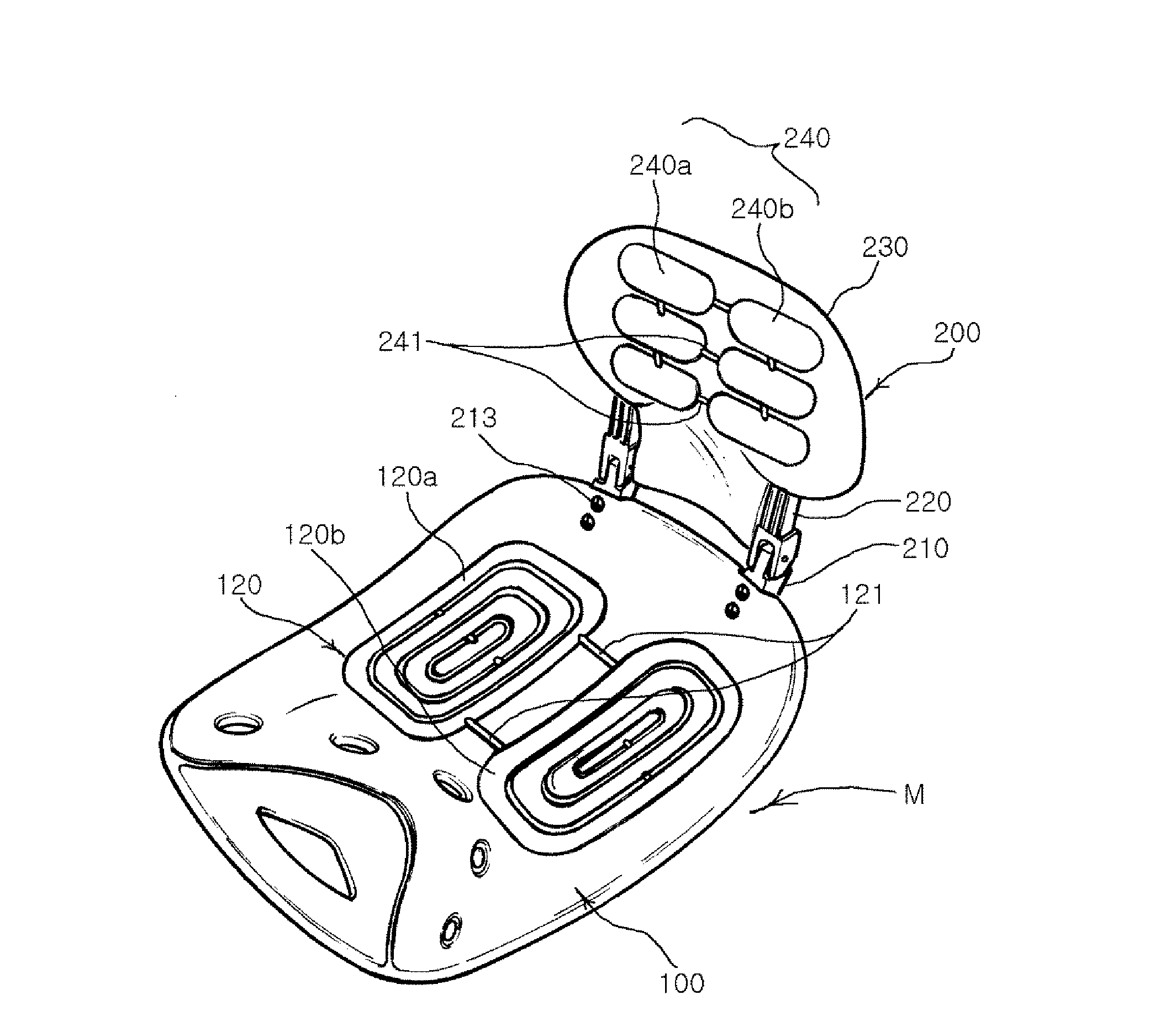
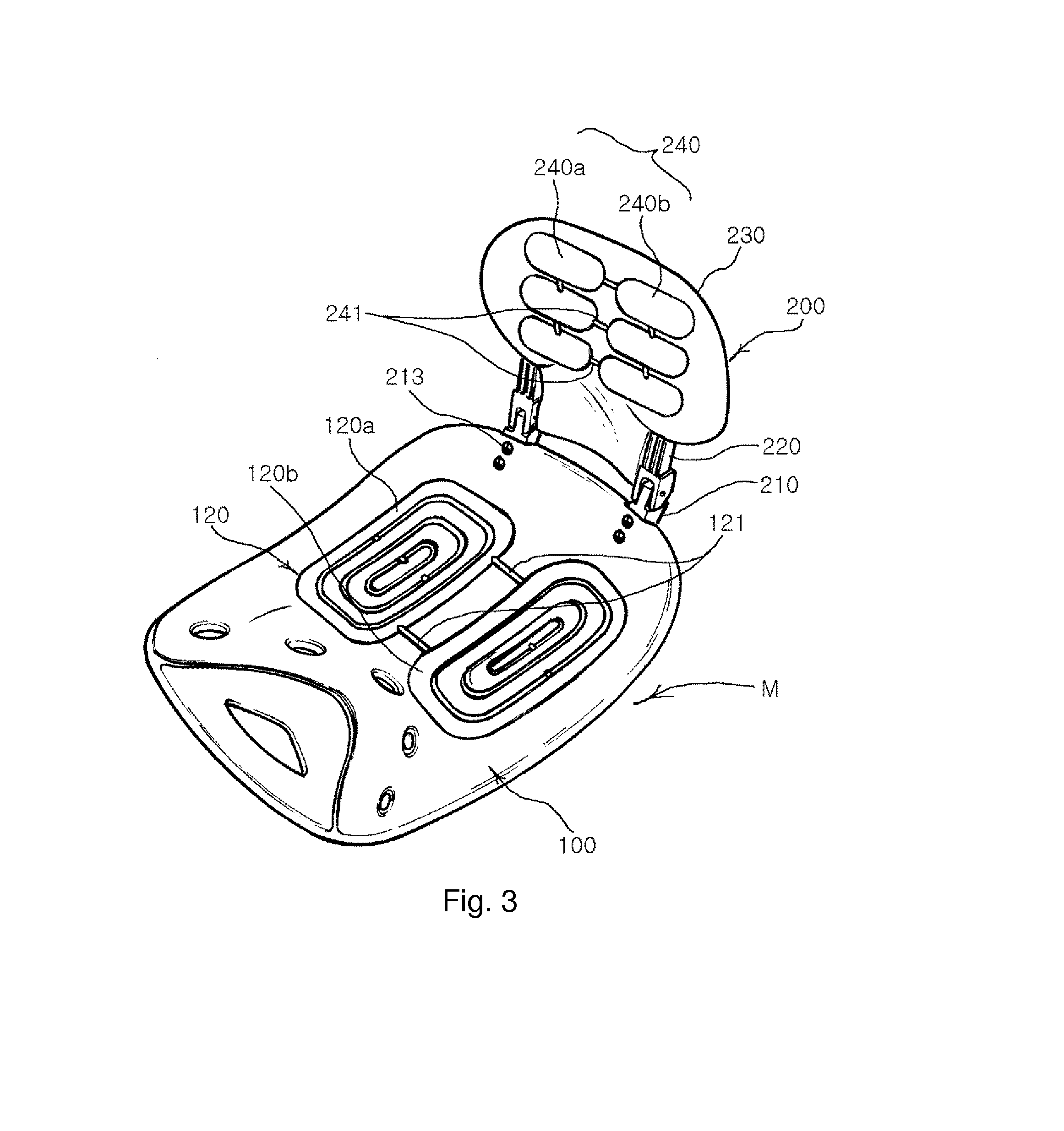
[0033]FIG. 3 is a perspective view showing a lumbar support seat for supporting lumbar vertebra portion according to a preferred embodiment of the present invention, FIG. 4 is an exploded perspective view of the lumbar support seat for supporting lumbar vertebra portion, FIG. 5 is a rear view showing the lumbar support seat for supporting lumbar vertebra portion, FIG. 6 is a longitudinal cross-sectional view showing the principal parts of the lumbar support seat for supporting lumbar vertebra portion, and FIG. 7 is a side view showing the principal parts of the lumbar support seat for supporting lumbar vertebra portion, wherein the base plate and the supporting frame of the lumbar support seat for the lumbar vertebra portion are folded.
[0034]Referring to FIGS. 3 to 7, the lumbar support seat M for supporting lumbar vertebra portion according to the present invention includes a seat main body 100, of which an upper central portion is curvedly indented so as to correspond to the shape of pelvis portion; and a lumbar supporting die 200 fixed at the upper portion of the rear end of the seat main body 100 for supporting lumbar vertebra portion.
[0035]In the seat main body 100 according to an embodiment of the present invention as shown in FIGS. 3 to 7, air cushions 120 are provided at the upper portion of a base 110, which is curvedly indented so as to correspond to the shape of the pelvis portion.
[0036]Each of the air cushions 120 of the seat main body 100 is divided into a left cushion section 120a and a right cushion section 120b, which are connected to each other via a small-diameter connection path 121.
[0037]In the lumbar support seat according to this embodiment as shown in FIGS. 3 to 7, each of the cushion sections 120a and 120b of the air cushions 120 of the seat main body 100, is formed of a central oval and a plurality of oval rings, which are concentric with the central oval and connected to the central oval or adjacent oval rings via the small-diameter connection path 121. However, the shape of the cushion sections 120a and 120b of the air cushions 120 of the seat main body 100 is not limited thereto but may be changed in a predictable range.
[0038]In the meantime, the lumbar supporting die 200 includes a pair of fixing frames 210, which are fixed to the seat main body 100; a pair of supporting frames 220, which are connected to the fixing frames 210 such that the supporting frames 220 may freely rotate in the back and forth direction; and the supporting plate 230 connected to the pair of supporting frames 220 such that the supporting plate 230 may move in the vertical direction.
[0039]In the lumbar support seat according to this embodiment as shown in FIGS. 3 to 7, each of the fixing frames 210 of the lumbar supporting die 200 has a hinge connection protrusion portion 211 that is provided at the front side of the upper end thereof, and a rotation guide combined with a stopper protrusion 212, which is provided at the rear side of the upper end thereof and curved in the shape of an arc, and a lower end portion, which is fixed to the seat main body 100 via a coupling bolt 213.
[0040]Each of the supporting frames 220 of the lumbar supporting die 200 has a hinge connection groove portion 221, which is provided in the center of a lower end thereof so as to be inserted in a hinge connection protrusion portion 211 of each of the fixing frames 210, an arc-shaped guide surface combined with a stopper groove portion 222 that is provided at the lower portion of a rear surface so as to correspond to the rotation guide combined with the stopper protrusion 212, and a plurality of latch grooves 223, which are provided at the upper portion of the rear surface in the vertical direction.
[0041]The supporting plate 230 of the lumbar supporting die 200 is indented in the center thereof so that the supporting plate 230 does not directly contact the lumbar vertebra portion, and has a shield section 231, which is integrally formed in the center of the lower portion of a front surface, and supporting frame coupling tubular portions 232, which are protrudedly provided at both sides of a rear surface and opened at the lower ends thereof. And, elastic holding pieces 234 are provided in the centers of the rear surfaces of the respective supporting frame coupling tubular portions 232 and have latch holding protrusions 233.
[0042]The support plate 230 of the lumbar supporting die 200 is provided with air cushions 240 on the front surface thereof.
[0043]Each of the air cushions 240 of the lumbar supporting die 200 is also divided into a left cushion section 240a and a right cushion section 240b, which are connected to each other via a small-diameter connection path 241, similarly to the air cushions 120 of the seat main body 100.
[0044]In the lumbar support seat according to this embodiment as shown in FIGS. 3 to 7, even though each of the cushion sections 240a and 240b of the lumbar supporting die air cushions 240 are disposed in the vertical direction and provided in the shape of a plurality of rectangular rods, which are connected to adjacent ones via the small-diameter connection paths 241, the shape of the respective cushion sections 240a and 240b of the lumbar supporting die air cushions 240 is not limited thereto and may be in a predictable range.
[0045]Reference sign 111, which is not explained above, indicates a handle hole and reference sign 224, which is not explained above, indicates a hinge connection pin.
[0046]Even though the lumbar support seat M according to the present invention as constructed above is intended to be placed on the floor, a chair or sofa, it may be independently used as a chair by preparing the seat main body 100 and the lumbar supporting die 200 with sufficient strength and mounting supporting legs to the lower end of the seat main body 100.
[0047]Now, the operational effects of the present invention will be described.
[0048]If a user sits on the lumbar support seat M of the present invention in the state that the lumbar support seat M is placed on a chair or sofa, the seat main body 100 may support the pelvis portion of a user via the upper central portion, which is curvedly indented correspondingly to the shape of the pelvis portion. Therefore, the user may sit on the chair in the right posture with the straight waist portion and keep the comfortable sitting posture without the pain of the waist portion.
[0049]Further, as the both buttock portions of the user push the both side edges of the concave seat main body 100, the rear portion of the seat main body 100 and the lumbar supporting die 200 provided thereto naturally push the lumbar vertebra portion and the spine so that the lumbar vertebra portion and the pelvis portion may be stably supported. Therefore, the lumbar vertebra portion is not applied with an excessive load in spite of long time sitting and the lumbar vertebra portion may be prevented from the damage or pain.
[0050]In the lumbar support seat M of the present invention, if the protrusion height of the supporting plate 230 of the lumbar supporting die 200 may be controlled as shown in the embodiment of FIGS. 3 to 7, it is possible to support the lumbar vertebra portion at a more comfortable position by lifting or lowering the supporting plate 230 according to the body type of a user.
[0051]In the meantime, in the lumbar support seat M of the present invention, the upper surface of the seat main body 100 and the front surface of the supporting plate 230 are respectively provided with the air cushions 120 and 240, promoting the sitting comfort.
[0052]Furthermore, each of the air cushions 120 and 240 is divided into the left cushion section 120a, 240a and the right cushion section 120b, 240b, which are connected to each other via the small-diameter connection path 121, 241. Therefore, the air charged in the left cushion section 120a, 240a slowly moves to the right cushion section 120b, 240b via the small-diameter connection path 121, 241 in the case that a load is concentrated on the left cushion section 120a, 240a. Accordingly, shock may be reduced in the process of the air flow from one of the air cushion section to the other one and comfort sitting feeling may be provided.
[0053]In the case that a load is concentrated on the right side pelvis portion or the left side lumbar vertebra portion, the air charged in the right cushion section 120b and 240b slowly moves to the left cushion section 120a, 240a via the small-diameter connection path 121, 241 in the similar way, and shock may be reduced in the process of the air flow from one of the air cushion section to the other one and comfort sitting feeling may be provided.
[0054]According to the lumbar support seat M of the present invention, the supporting plate 230 and the supporting frame 220 of the lumbar supporting die 200 may be rotated toward the seat main body 100 as shown in FIG. 7 so as to fold the same in a small volume in the case of package or transport. In addition, the lumbar support seat M may be readily carried during use by holding the handle hole 111, which is provided in the front portion of the seat main body 100.
[0055]Although preferred embodiments of the present invention have been described for illustrative purposes, those skilled in the art will appreciate that various modifications, additions and substitutions are possible, without departing from the scope and spirit of the invention as disclosed in the accompanying claims.
BRIEF EXPLANATION OF REFERENCE SIGNS
[0056] M: lumbar support seat [0057] 100: seat main body [0058] 110: base [0059] 120: air cushions [0060] 121: connection path [0061] 120a: left cushion section [0062] 120b: right cushion section [0063] 200: lumbar supporting die [0064] 210: fixing frame [0065] 211: hinge connection protrusion portion [0066] 212: rotation guide combined with stopper protrusion [0067] 213: coupling bolt [0068] 220: supporting frame [0069] 221: hinge connection groove portion [0070] 222: arc-shaped guide surface combined with stopper groove portion [0071] 223: latch groove [0072] 230: supporting plate [0073] 231: shield section [0074] 232: supporting frame coupling tubular portion [0075] 233: latch holding piece [0076] 234: elastic holding piece [0077] 240: air cushions [0078] 240a: left cushion section [0079] 240b: right cushion section [0080] 241: connection path

PUM

no PUM

Description & Claims & Application Information

We can also present the details of the Description, Claims and Application information to help users get a comprehensive understanding of the technical details of the patent, such as background art, summary of invention, brief description of drawings, description of embodiments, and other original content. On the other hand, users can also determine the specific scope of protection of the technology through the list of claims; as well as understand the changes in the life cycle of the technology with the presentation of the patent timeline. Login to view more.

Similar technology patents

Device for assembling panels

ActiveUS20190176318A1stably supportwell adjustment
Owner:ONA GONZALEZ FRANCISCO JAVIER

Tape rule having reoriented measuring blade

InactiveUS20060156572A1stably support
Owner:STEVEN W LEWIS +1

Production line for afforestation

PendingUS20200196517A1walk stablystably support
Owner:SU ZHENGYONG

Child bassinet

PendingUS20220031089A1simple constructionstably support
Owner:WONDERLAND SWITZERLAND AG

Display Apparatus

InactiveUS20080098639A1easily placestably support
Owner:KING JIM CO LTD

Classification and recommendation of technical efficacy words

  • stably support
  • prevent stress

Support device for supporting frames and other objects from a structure

InactiveUS6682033B1stably supportreadily remove
Owner:COHEN MARK +1

Automatic workpiece clamp and support

InactiveUS20090184450A1stably support
Owner:WUERTHNER MATTHEW WAYNE

Regulated fluid dispensing system packaging

InactiveUS20090283579A1easily graspstably support
Owner:MILLERCOORS

Foot, leg, and arm support for exercise

InactiveUS20120329621A1reduce chancestably support
Owner:LORENTZ II ROBERT A

Controller for monitor

InactiveUS20070114342A1stably supporteasily change inclination angle
Owner:MAMEDEN

Glass film laminate, glass roll of the laminate, method of protecting end face of glass film, and method of producing glass roll

ActiveUS20100260964A1improve handleabilityprevent stress
Owner:NIPPON ELECTRIC GLASS CO LTD

Demolition claw

InactiveUS20070245568A1prevent stressminimize cost
Owner:ATLAS COPCO CONSTR TOOLS GMBH

Die coat perimeter to enhance semiconductor reliability

InactiveUS20080197514A1enhance reliabilityprevent stress
Owner:ANALOG DEVICES INC

Abdominal exercising apparatus and method

InactiveUS20090305856A1prevent stress
Owner:CORE FITNESS SYST +1

Light emitting device

ActiveUS20140140079A1prevent stress
Owner:NICHIA CORP
Why Eureka
Try Eureka