Surgical glove systems and method of using the same

a glove system and surgical technology, applied in the field of surgical glove systems, can solve the problems of entanglement problems, shorten the effective working length of the instrument, and the difficulty of easy access of the instrument between surgeons, so as to eliminate the problem of entanglemen

Active Publication Date: 2013-02-21
SCHNEIDER ANDREW I
View PDF11 Cites 13 Cited by
  • Summary
  • Abstract
  • Description
  • Claims
  • Application Information

AI Technical Summary

Benefits of technology

[0007]This invention relates to a surgical system that includes one or more surgical gloves having support systems such as, but not limited to, one or more light sources, an electrical cautery device, a suction source, and an irrigation supply. The surgical system may also include a surgical gown. Each surgical glove may include one or more of the light sources, electrical cautery devices, suction sources, and irrigation sources positioned on fingers of the surgical glove. The support systems may be controlled with switches positioned on the fingers upon which each support system is positioned. The switches may be operable with the thumb of the human hand wearing the surgical glove. The surgical system may also include a surgical gown having a connection system for attaching support conduit supporting the support systems to the surgical gown. The surgical system enables a surgeon to have a plurality of support systems immediately available and eliminates entanglement problems endemic with conventional systems. The support systems may be attached to the surgical glove(s) in various configurations to optimize the configuration for a surgeon such that the systems are located for facility of use and in a position where the systems are unlikely to obstruct or conflict with the general use of the surgeon's hand or the use of surgical instruments, and in a manner which optimizes the simultaneous, synergistic use of more than one support system.
[0015]In one embodiment, the support conduits extend from the dorsal wrist area of the surgical glove(s) along the lateral or ulnar aspect of the surgeon's arm(s), toward the shoulder, then posteriorly around the shoulder and finally caudally down the surgeon's back, where they can be directly connected to the appropriate connections. In an alternative embodiment, the support conduits may extend along medial or radial aspects of the arms, into the axilla of the shoulder, then over the lower region of the scapula and caudally down the surgeon's back. In the first embodiment, the connection system may include attachment devices on lateral aspects of the surgical gown corresponding to a forearm, upper arm, lateral shoulder, scapular, and lower lateral back areas of the surgical gown to retain support conduits extending from the surgical glove, along an arm, over a shoulder, and along a back. The attachment devices effectively, visually and physically, eliminate the independent presence of electrical wires, conduits, and other support conduits, in the surgical field. In addition, the attachment devices assist in preventing accidental entanglement or contamination of these entities without inhibiting the range of motion of a surgeon's arm or shoulder.
[0016]The invention may also be directed to a method of performing a surgical procedure in which the need to retrieve surgical implements that beforehand were rested on the surgical field is eliminated. In particular, the method may include attaching at least one surgical system to a glove worn by a person performing the surgical procedure before commencing the surgical procedure. The person conducting the surgical procedure may be, but is not limited to being, a surgeon or other appropriate person. At least one surgical instrument may be attached to the first surgical system such that the at least one surgical instrument extends proximate to a distal end of a finger of the glove to which the first surgical system is attached. The first surgical system may remain attached to the person throughout the surgical procedure eliminating need for a surgical implement assistant. For instance, the surgeon need not rest instruments on the surgical field and constantly pick up the instruments or request the instruments from an assistant. Rather, the instruments may remain attached to the surgeon throughout the duration of the surgery. Such a method enables a surgeon to work more independently and thus maintain focus on the surgical procedure.

Problems solved by technology

Unfortunately, as well intention and organized as the setup may be, the cords and conduits invariably become entangled during the course of a procedure, thereby creating frequent frustration and time delay.
Once entangled, instruments become more difficult to easily reach onto pass between surgeons.
Entanglement of instrument wire and cords also shortens the effective working length of the instruments and further interferes with their accurate and unobstructed use.
Often times, the electrical cautery or suction supply is accidentally dropped from the surgical field onto the floor, thereby compromising their sterility and requiring replacement.
Unfortunately, during a procedure, the scrub nurse may be occupied for a variety of reasons and have difficulty providing the irrigation in a timely fashion.
For example, a scrub nurse is commonly asked to hold a retractor, or other instrument in the surgical field, and is not available to easily turn around and grab the irrigation when needed.
However, there are still challenges to overcome with these systems, including instances where the suction line becomes clogged, a surgical instrument fires accidentally, or conventional surgical systems need to be used in addition to the gloves described in the Schneider patents.

Method used


Image

  • Surgical glove systems and method of using the same
  • Surgical glove systems and method of using the same
  • Surgical glove systems and method of using the same

Examples


Embodiment Construction

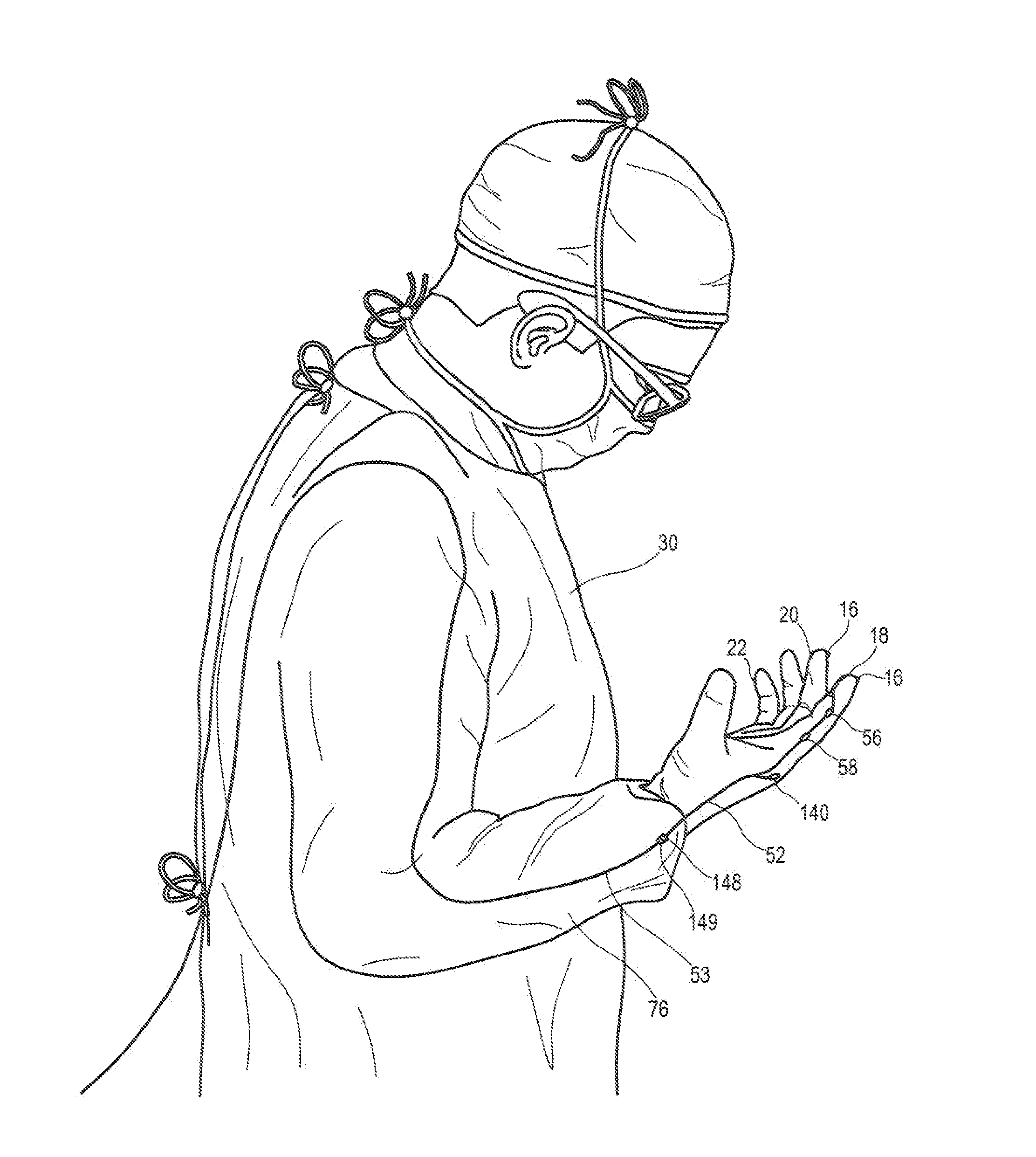
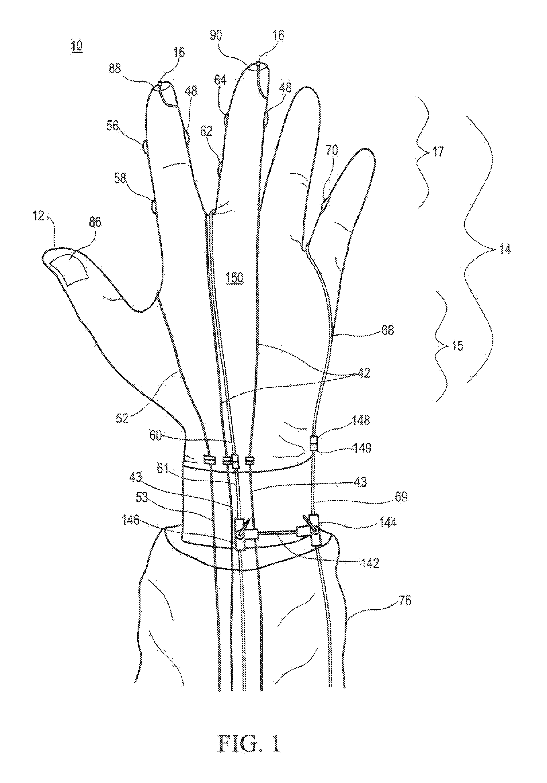
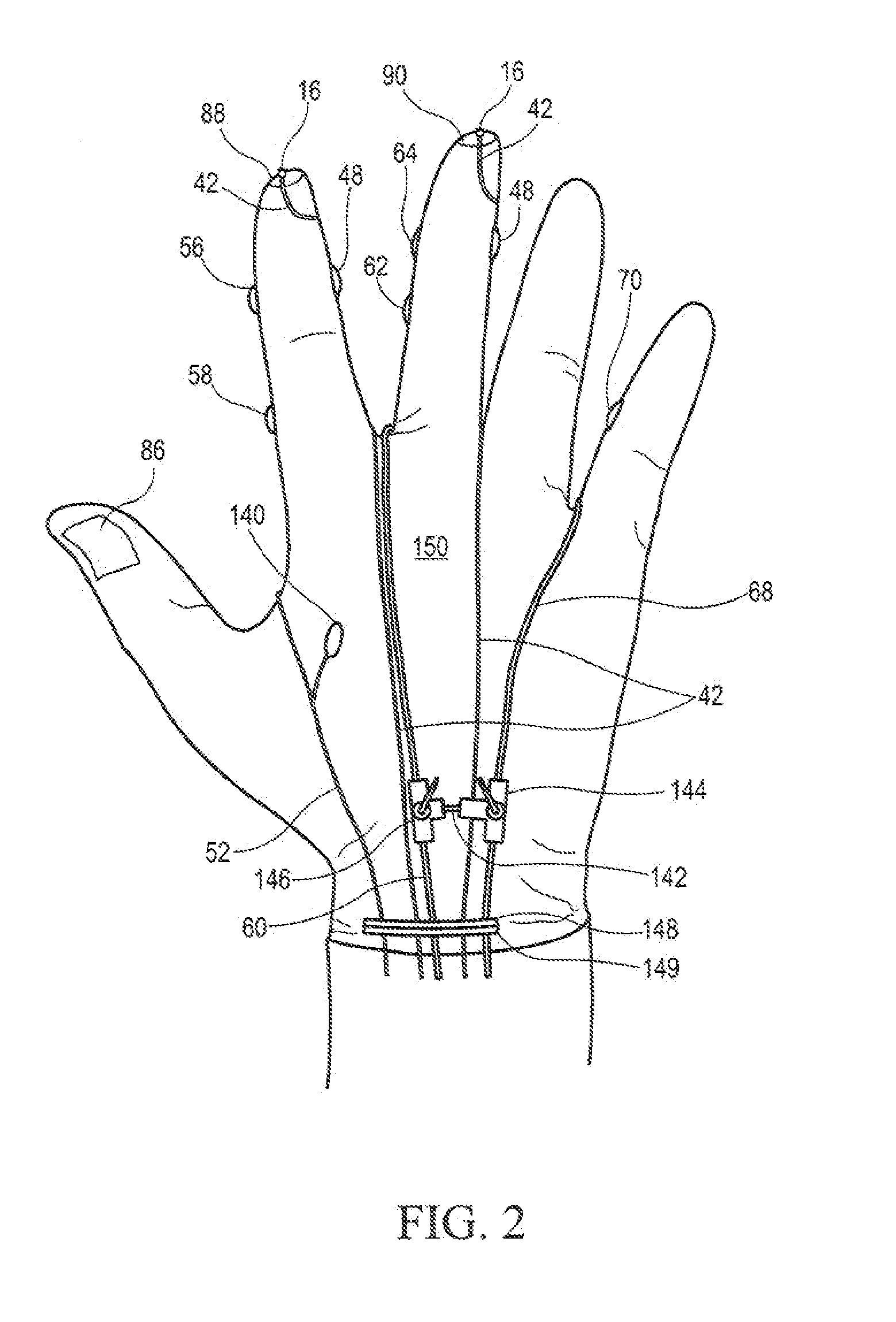
[0032]As shown in FIGS. 1-13, this invention is directed to surgical systems 10 that include one or more surgical gloves 12, 13 having support systems 14 such as, but not limited to, one or more lights 16, electrical cautery 18, suction 20 and irrigation 22. The surgical glove 12, 13 may include one or more of the lights 16, electrical cautery 18, suction 20 and irrigation 22 positioned on distal ends 24 of fingers 26 of the surgical gloves 12, 13. The support systems 14 may be controlled with switches (e.g., 48, 56, 58, 62, 64, 70 and 140) positioned on the fingers of the glove 12, 13 upon which each support system 14 is positioned. The switches may be operable with the thumb of the human hand to which the surgical glove 12, 13 is attached. The surgical system 10 may also include a surgical gown 30 having a connection system 32 for attaching support conduit 34 of the support systems 14 to the surgical gown 30. The surgical system 10 enables a surgeon to have a plurality of support ...


PUM


Abstract

A surgical system including one or two surgical gloves having support systems such as, but not limited to, lights, electrical cautery, suction, and irrigation, attached to fingers of the surgical glove. The support systems may be controlled with switches positioned on the fingers upon which each support system is positioned. The switches may be operable with the thumb on the human hand upon which the surgical glove is attached. The system may also include (i) a safety switch coupled to the glove for controlling the first surgical system so that the first surgical system will not operate unless both the first switch and the safety switch are actuated, or (ii) a shunt for controlling fluid flow between the first and second conduits. Different support systems may be included in each glove for a bilateral system or may be combined into a single glove system.

Description

CROSS-REFERENCE TO RELATED APPLICATIONS[0001]This application is a continuation-in-part of U.S. patent application Ser. No. 13 / 450,958, filed Mar. 19, 2012, which is a continuation of U.S. patent application Ser. No. 13 / 081,345 filed, Apr. 6, 2011, now U.S. Pat. No. 8,182,479, which is a continuation application of U.S. patent application Ser. No. 11 / 591,305 filed Nov. 1, 2006, which issued as U.S. Pat. No. 7,931,648, which is continuation-in-part application of U.S. patent application Ser. No. 11 / 335,050, filed Jan. 19, 2006, which issued as U.S. Pat. No. 7,951,145 and this application claims priority to U.S. Provisional Application No. 61 / 539,350, entitled “Surgical Glove Systems and Methods of Making the Same,” filed Sep. 26, 2011, the entireties of which are all incorporated by reference herein.FIELD OF THE INVENTION[0002]This invention is directed generally to surgical systems, and more particularly to surgical systems for providing support to a surgeon during surgery.BACKGROUN...

Claims


Application Information

Patent Timeline
Patent Type & Authority Applications(United States)
IPC IPC(8): A61B18/18
CPCA61B18/14A61B19/04A61B2019/2273A61B2019/5206A61B17/320068A61B19/08A61B90/30A61B42/00A61B46/00A61B2034/741A61B2090/306A61B42/10A61B2017/320069A61B2017/32007A61B2018/00595A61B2218/002A61B2218/007
Inventor SCHNEIDER, ANDREW I.
Owner SCHNEIDER ANDREW I
Why Eureka
Try Eureka