Method of punching damper with use of hollow punch, punching apparatus for the method, and attaching apparatus with the punching apparatus

Active Publication Date: 2013-02-28
NHK SPRING CO LTD
View PDF3 Cites 21 Cited by
  • Summary
  • Abstract
  • Description
  • Claims
  • Application Information

AI Technical Summary

Benefits of technology

[0012]According the aspect, the exfoliative member is bent away from a cut edge of the damper around the projection part by the punch cutting out the

Problems solved by technology

In such head suspension, data errors occur due to off tracks that are generated by turbulence (wind excitation), a natural vibration or the like at the time of the rotation of the disc.
In this technique, the punched dampers must be aligned between t

Method used


Image

  • Method of punching damper with use of hollow punch, punching apparatus for the method, and attaching apparatus with the punching apparatus
  • Method of punching damper with use of hollow punch, punching apparatus for the method, and attaching apparatus with the punching apparatus
  • Method of punching damper with use of hollow punch, punching apparatus for the method, and attaching apparatus with the punching apparatus

Examples


first embodiment

[0033]the present invention will be explained in detail with reference to drawings.

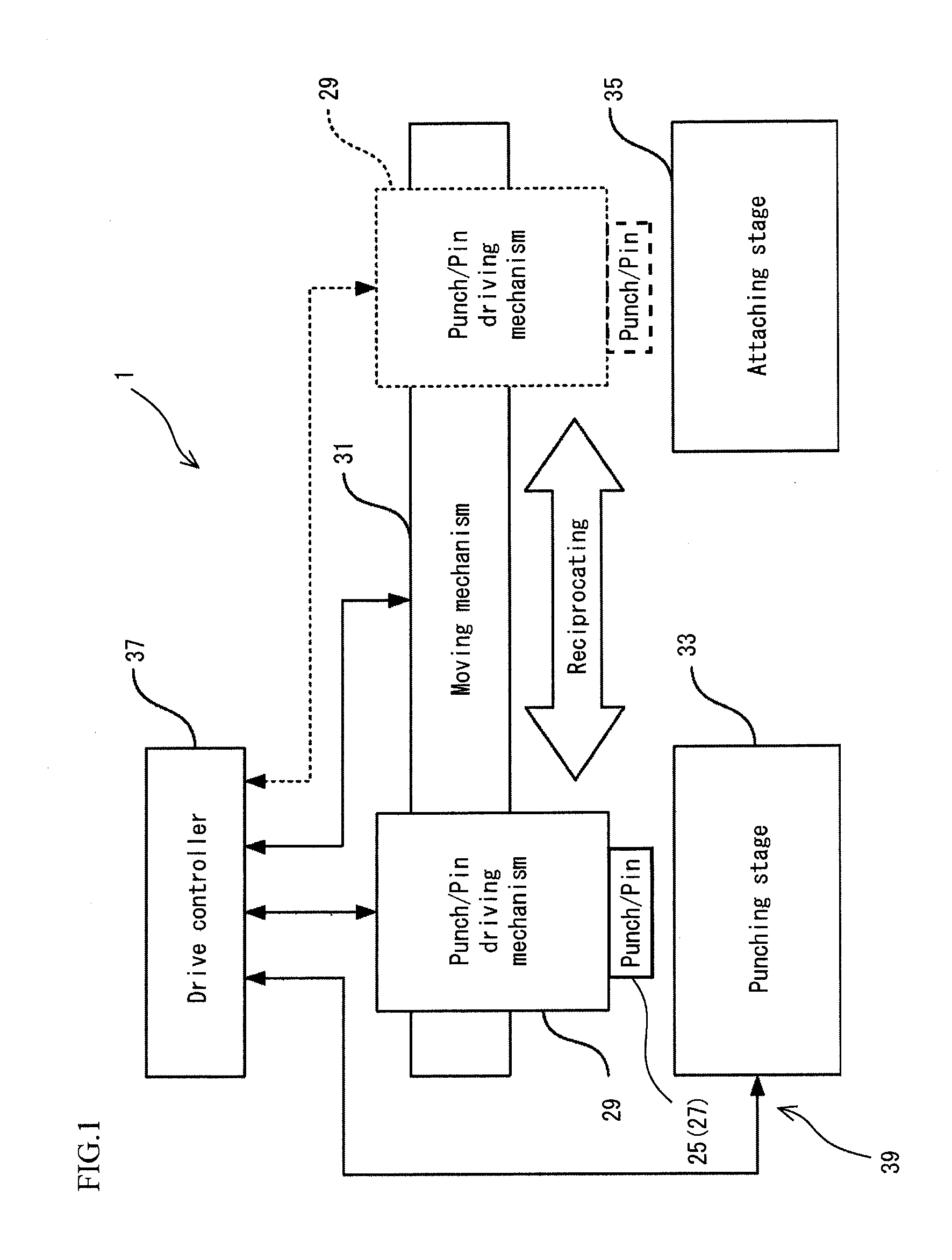
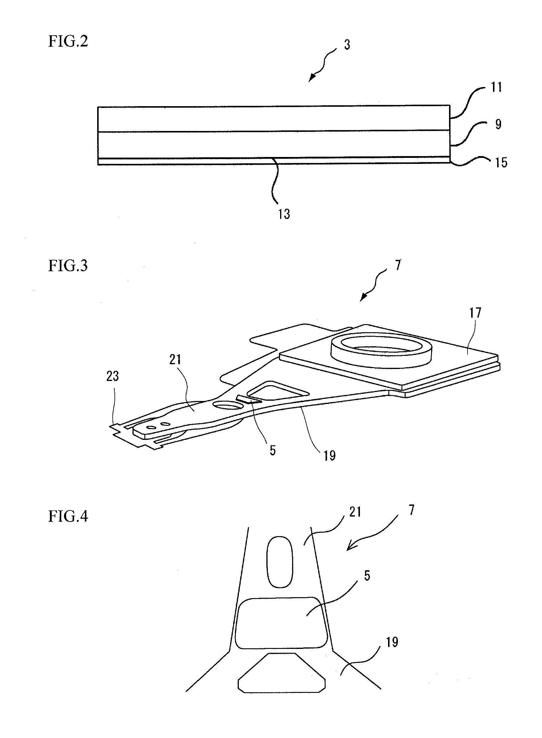
[0034]FIG. 1 is a block diagram schematically illustrating an attaching apparatus of a damper, FIG. 2 is a side view illustrating a layered structure of a damper material, FIG. 3 is a perspective view schematically illustrating a head suspension on which the damper is attached, and FIG. 4 is a plan view partly illustrating the head suspension of FIG. 3. FIGS. 3 and 4 indicate the same head suspension 7 with a damper 5, however, the head suspensions 7 in FIGS. 3 and 4 are indicated with slight differences.

[0035]According to the first embodiment, an attaching apparatus 1 of FIG. 1 punches a damper 5 out from a damper material 3 of FIG. 2 to hold the punched damper. The held damper 5 is attached to an objective part of a head suspension 7 of FIGS. 3 and 4.

[0036]The damper material 3 being an object to be punched includes a viscoelastic body layer 9 made of adhesive compound and a constraint layer 11 inte...

second embodiment

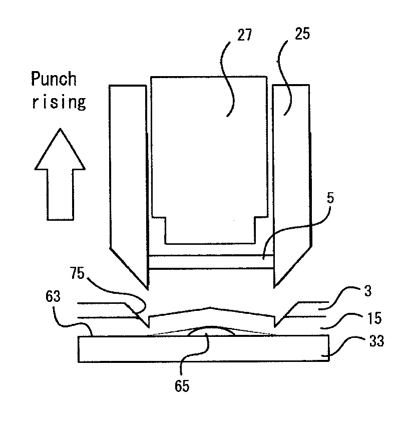
[0117] the punching stage 33A has a discrete supporting pin 65A movable in a punching direction of a punch 25. Namely, the punching stage 33A has a through-hole 77 formed therethrough in a thickness direction. Into the through-hole 77, the supporting pin 65A is inserted and is supported movable backward and forward in the punching direction.

[0118]A front end of the supporting pin 65A protrudes from a supporting surface 63 of the punching stage 33A. The base end of the supporting pin 65A is attached to an actuator (not illustrated) that moves the supporting pin 65A backward and forward. The movement of the supporting pin 65A is controlled by a drive controller 37. Under the control of the drive controller 37, the supporting pin 65A retracts so as not to protrude from the supporting surface 63 when the damper material 3 is fed on the punching stage 33A and advances so as to protrude from the supporting surface 63 when the damper 5 is punched out.

[0119]The second embodiment smoothly fe...

third embodiment

[0122] a punching stage 33B has no supporting pin and a liner 15B set on a damper material 3 integrally has a projection 33B as a projection part. The projection 33B is formed at each objective part of the damper material 3 to be punched out as a damper 5.

[0123]The third embodiment easily and accurately positions the projection 33B between a supporting surface 63B and the liner 15B while using an existing punch and an existing punching stage without a supporting pin.

[0124]This easily and accurately realizes the method of punching the damper 5 according to the present invention.

[0125]In addition, the third embodiment provides the same effects as the first embodiment.


PUM

PropertyMeasurementUnit
Flexibilityaaaaaaaaaa
Shapeaaaaaaaaaa
Elasticityaaaaaaaaaa

Abstract

A method punches a damper out from a damper material that is detachably attached on a flexible exfoliative member through an attaching surface of the damper material with use of a hollow punch. The method includes steps of setting the damper material on a supporting surface, positioning a projection part between the exfoliative member and the supporting surface, and punching the damper out from the damper material by cutting the damper material around the projection part by the hollow punch without punching the exfoliative member.

Description

BACKGROUND OF THE INVENTION[0001]1. Field of the Invention[0002]The present invention relates to a method of punching a damper to be attached to an objective part of, for example, a head suspension of a hard disk, to a punching apparatus for the method and to an attaching apparatus with the punching apparatus.[0003]2. Description of the Related Art[0004]A hard disk drive has a disk and a head suspension for supporting a head. The head suspension allows the head to slightly float from the disk to read / write signals when the disk rotates at high speed. In such head suspension, data errors occur due to off tracks that are generated by turbulence (wind excitation), a natural vibration or the like at the time of the rotation of the disc.[0005]To solve this problem, JP2001-067635A discloses a vibration damping technique that attaches a damper to a head suspension, the damper including a viscoelastic body layer and a constraint layer laminated on the viscoelastic body layer.[0006]When the ...

Claims


Application Information

Patent Timeline
IPC IPC(8): B26D7/18B26F1/14
CPCB26F1/14B26F1/02B26D7/1818G11B5/4833Y10T83/06Y10T83/2077
Inventor SOTOKAWA, KOJIOKUBO, NAOTO
Owner NHK SPRING CO LTD
Why Eureka
Try Eureka