Fuel Injector For Dual Fuel Common Rail System

a fuel injector and common rail technology, applied in the direction of fuel injection apparatus, charge feed system, combustion engine, etc., can solve the problems of difficult space for all of the plumbing and hardware associated, and the difficulty of successful ignition of gaseous fuels

Inactive Publication Date: 2013-02-28
CATERPILLAR INC
View PDF9 Cites 49 Cited by
  • Summary
  • Abstract
  • Description
  • Claims
  • Application Information

AI Technical Summary

Benefits of technology

[0004]In one aspect, a fuel injector includes an injector body that defines a first nozzle outlet set, a first fuel inlet, a second nozzle outlet set, a second fuel inlet and a drain outlet. Exposed in the injector body are a first nozzle chamber fluidly connected to the first fuel inlet, a second nozzle chamber fluidly connected to the second fuel inlet, a first control chamber fluidly connected to the first fuel inlet, and a second control chamber fluidly connected to the first fuel inlet. A first needle control valve is positioned in the injector body and includes a first control valve member movable between a first position in contact with a conical seat to close a fluid connection between the first control chamber and the drain outlet, and a second position out of contact with the conical seat to open the first fluid connection. The second needle control valve is positioned in the injector body and includes a second control valve member movable between a first position in contact with a conical seat to close a second fluid connection between the second control chamber and the drain outlet, and a second position out of contact with the conical seat to open the second fluid connection. A first solenoid actuator has a first armature operably coupled to the first needle control valve, and a second electrical actuator has a second armature operably coupled to the second needle control valve.
[0005]In another aspect, a dual fuel system includes a plurality of fuel injectors that have a non-injection configuration, a liquid fuel injection configuration, a gaseous fuel injection configuration and a combined fuel injection configuration. A gaseous fuel common

Problems solved by technology

However, gaseous fuels are well known for the difficulty in attaining successful ignition.
Practical spatial limitations in and around an engine often make it difficult to find space for all of the plumbing and hardware associated with supplying two different fuels

Method used


Image

  • Fuel Injector For Dual Fuel Common Rail System
  • Fuel Injector For Dual Fuel Common Rail System
  • Fuel Injector For Dual Fuel Common Rail System

Examples


Embodiment Construction

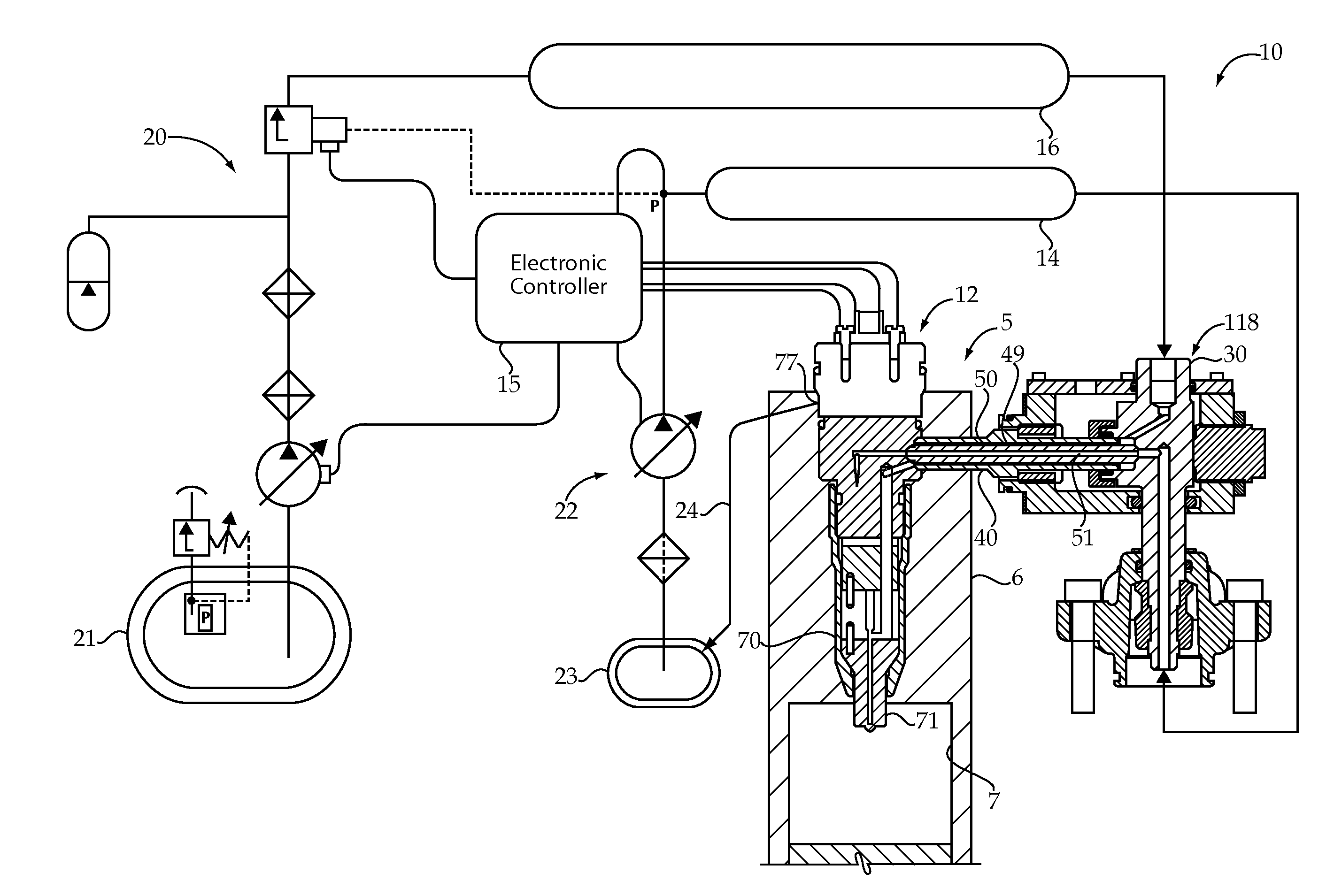
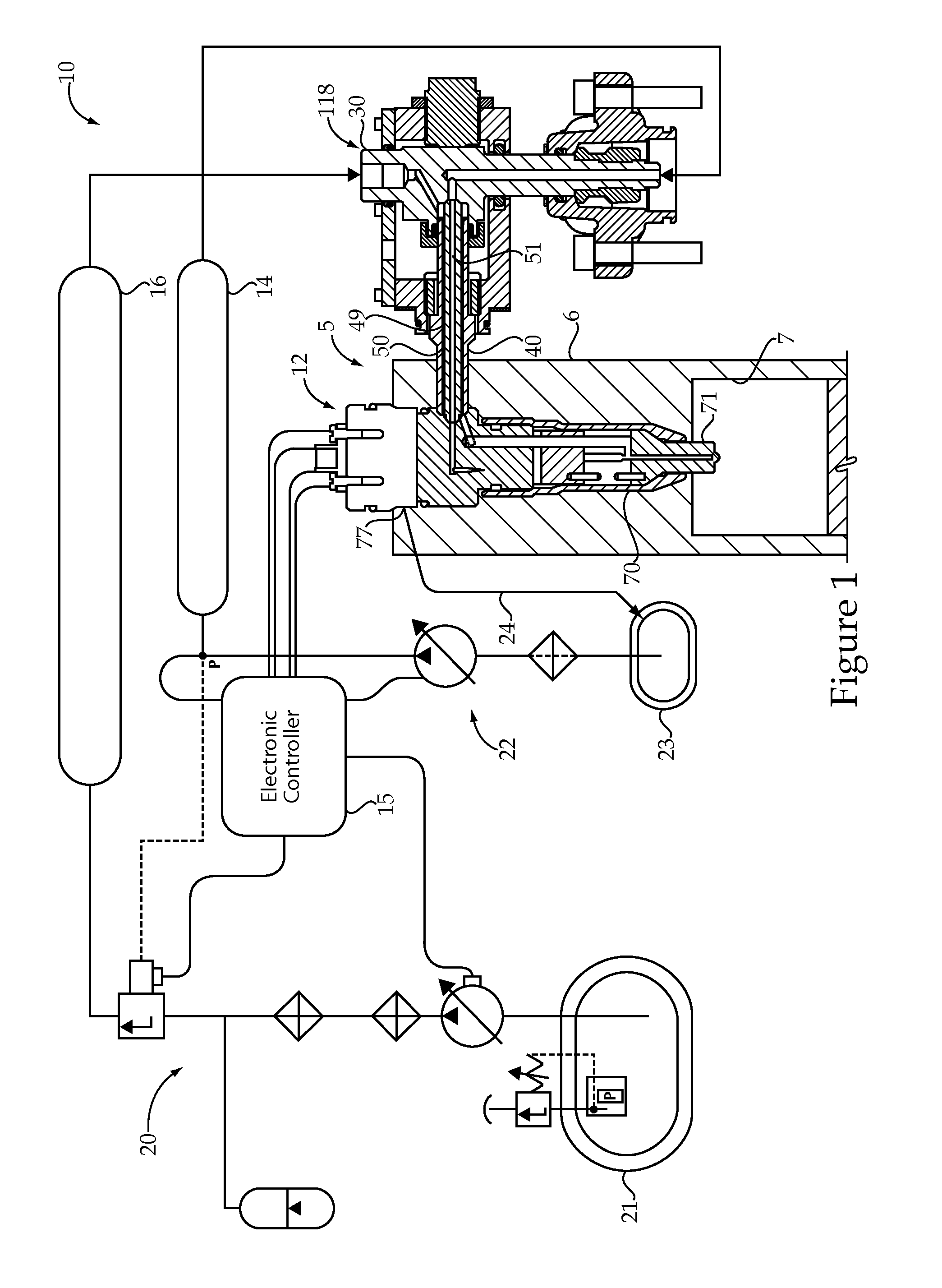
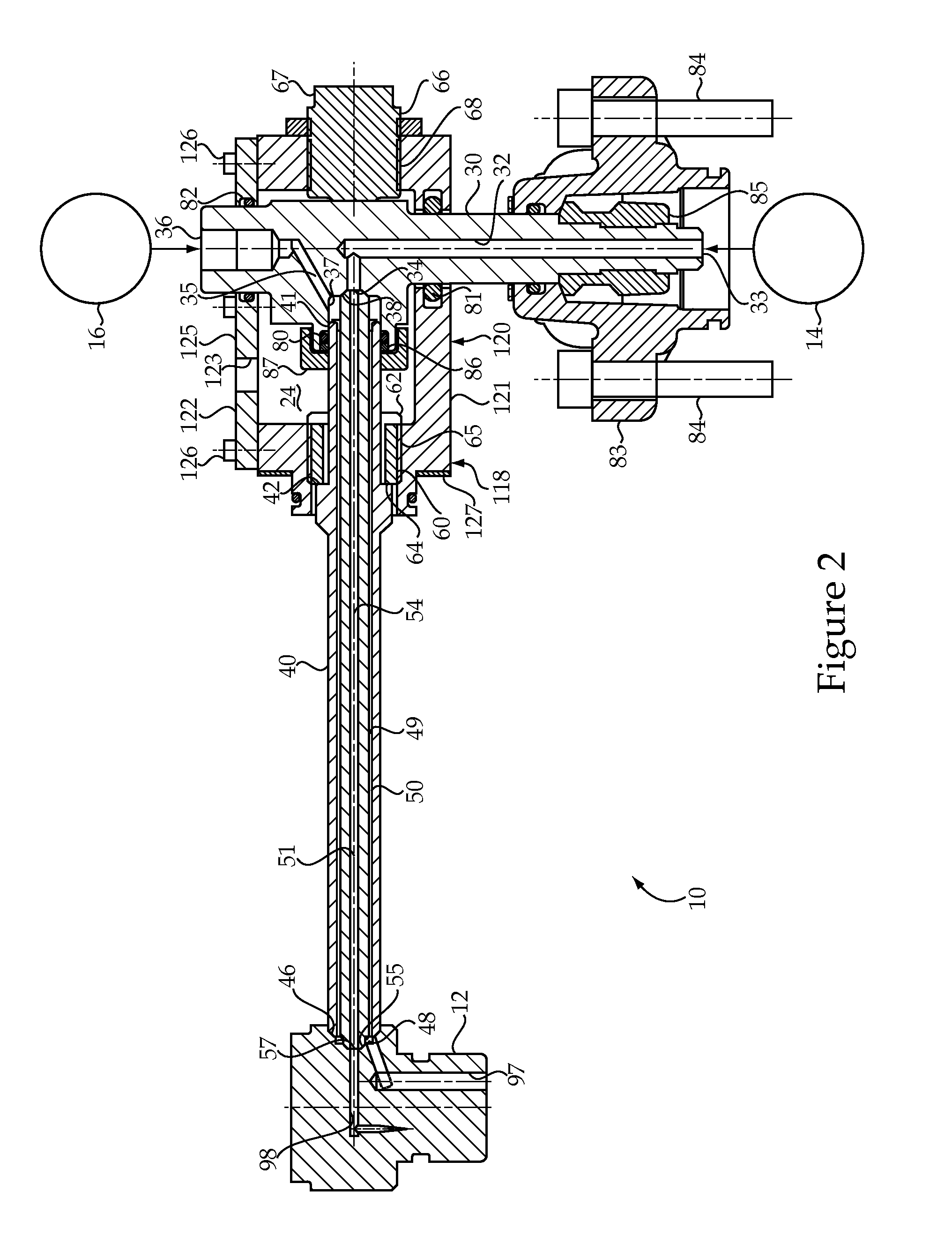
[0014]Referring to FIG. 1, an engine 5 according to the present disclosure utilizes a dual fuel common rail system 10. Engine 5 includes an engine housing 6 that defines a plurality of cylinders 7, only one of which is shown. The dual fuel system 10 includes a plurality of fuel injectors 12 (only one shown) that each include an injector body 70 with a tip component 71 positioned for direct injection of gaseous fuel and / or liquid fuel into one of the engine cylinders 7. The dual fuel system 10 includes a plurality of concentric outer tubes 50 and inner tubes 40 that each extend into engine housing 6 between a quill 30 and one of the fuel injectors 12. Each of the inner tubes 50 is compressed between a conical seat on an associated quill 30 and a conical seat on one of the fuel injectors 12. Thus, each engine cylinder 7 has one associated fuel injector 12, one outer tube 40, one inner tube 50 and one quill 30. The dual fuel system 10 includes a gaseous fuel common rail 16 that is flui...


PUM


Abstract

A duel fuel system includes a plurality of fuel injectors that have a non-injection configuration, a liquid fuel injection configuration, a gaseous fuel injection configuration and a combined fuel injection configuration. Each of the fuel injectors is fluidly connected to a gaseous fuel common rail and a liquid fuel common rail. Each of the fuel injectors includes a three way gas control valve and a three way liquid control valve that move along a common centerline. A gas control chamber of each fuel injector is fluidly connected to the liquid fuel common rail by two passages in parallel when the gas control valve member is in a first position corresponding to the non-injection configuration. The liquid control chamber of each fuel injector is also fluidly connected to the liquid fuel common rail by two passages in parallel when the liquid control valve is in a first position, again corresponding to the non-injection configuration.

Description

TECHNICAL FIELD[0001]The present disclosure relates generally to dual fuel common rail systems, and more particularly to a dual fuel injector for fueling an engine with gaseous and liquid fuels, respectively.BACKGROUND[0002]Gaseous fuel engines are known for their ability to burn clean relative to their compression ignition engine counterparts. However, gaseous fuels are well known for the difficulty in attaining successful ignition. Some gaseous fuel engines utilize a spark plug, whereas other engines are known for utilizing a small amount of distillate diesel fuel that is compression ignited to in turn ignite a larger charge of gaseous fuel. Practical spatial limitations in and around an engine often make it difficult to find space for all of the plumbing and hardware associated with supplying two different fuels to each combustion chamber. U.S. Pat. No. 7,373,931 teaches a dual fuel engine that utilizes a small quantity and compression ignited distillate diesel fuel to ignite a l...

Claims


Application Information

Patent Timeline
IPC IPC(8): F02M51/00
CPCF02M63/008F02M43/04F02M47/027F02M63/0019F02D19/0694Y02T10/36F02M2200/44F02M63/0064F02M63/0035F02M55/02F02D19/10Y02T10/30F02D19/0647
Inventor KIM, HOISAN
Owner CATERPILLAR INC
Why Eureka
Try Eureka