Self-inflating tire

a self-inflating, tire technology, applied in the direction of inflatable tyres, tire measurements, vehicle components, etc., can solve the problems of reducing vehicle braking and handling performance, reducing tire life, etc., and achieve the effect of improving traction

Active Publication Date: 2013-02-28
THE GOODYEAR TIRE & RUBBER CO
View PDF4 Cites 43 Cited by
  • Summary
  • Abstract
  • Description
  • Claims
  • Application Information

AI Technical Summary

Benefits of technology

[0021]“Sipe” means small slots molded into the tread elements of the tire that subdivide the tread surface and improve traction, s

Problems solved by technology

Accordingly, drivers must repeatedly act to maintain tire pressures or they will see reduced fuel economy, tire life and reduced vehicle braking and hand

Method used


Image

  • Self-inflating tire
  • Self-inflating tire
  • Self-inflating tire

Examples


first embodiment

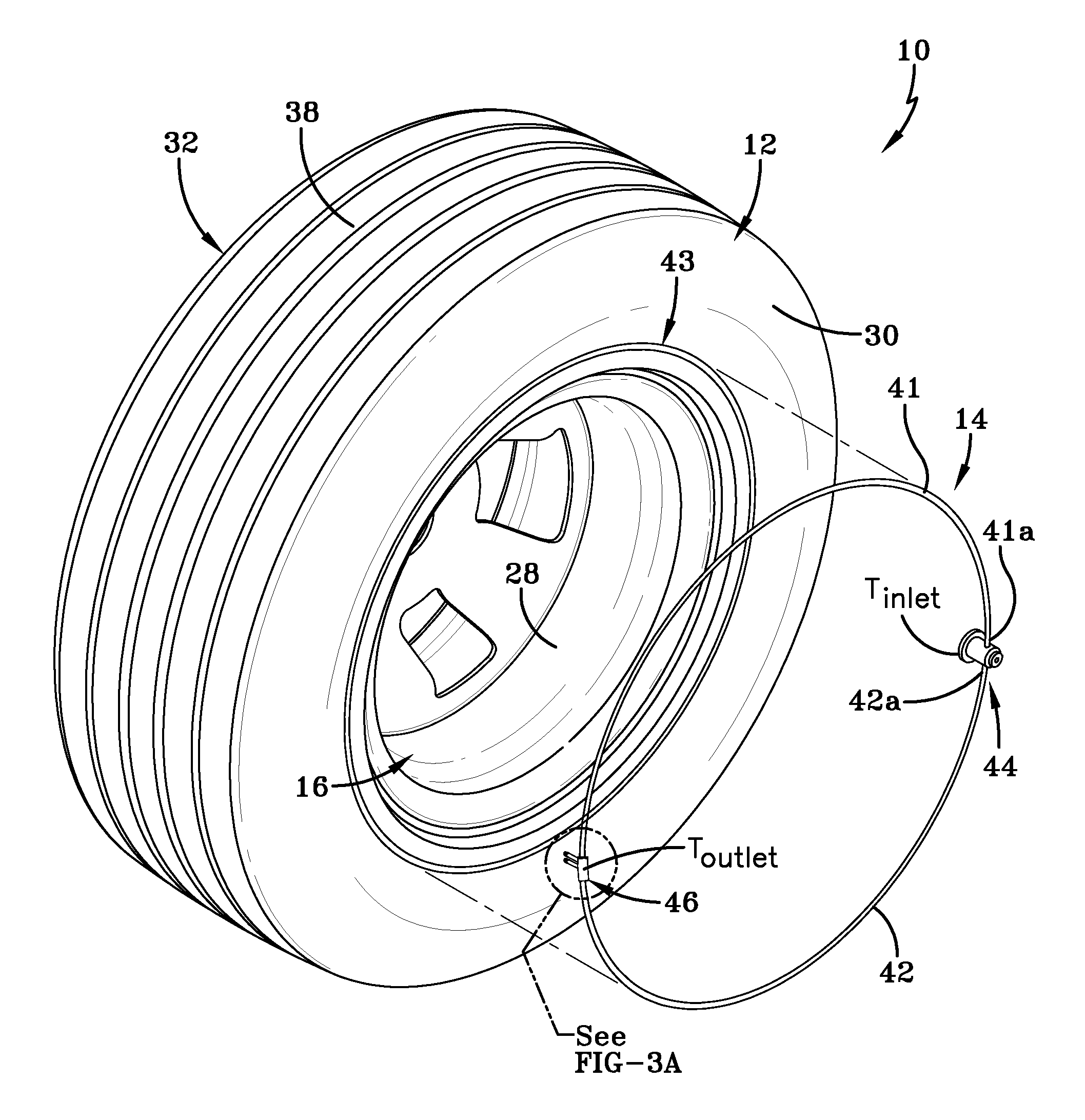
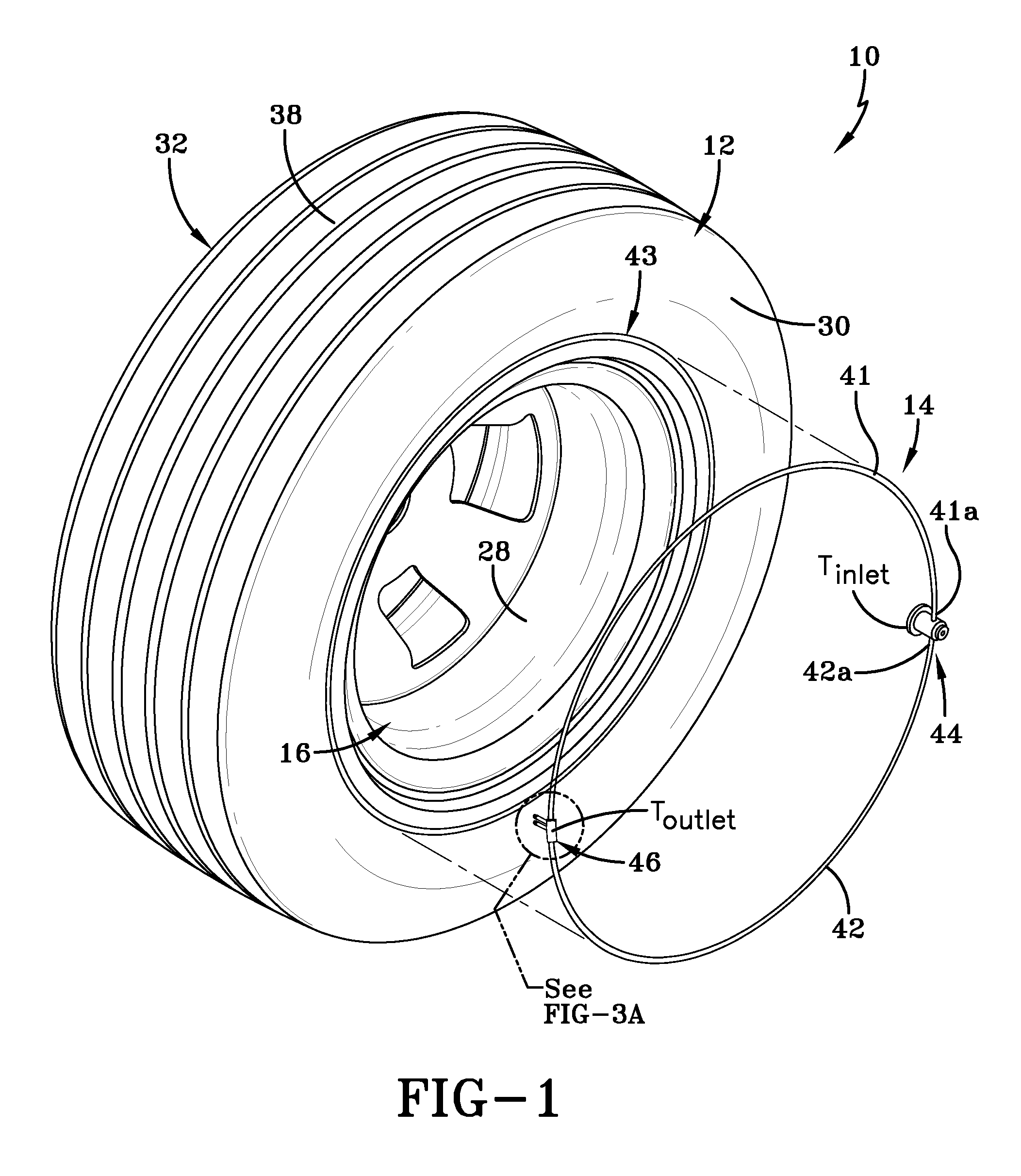
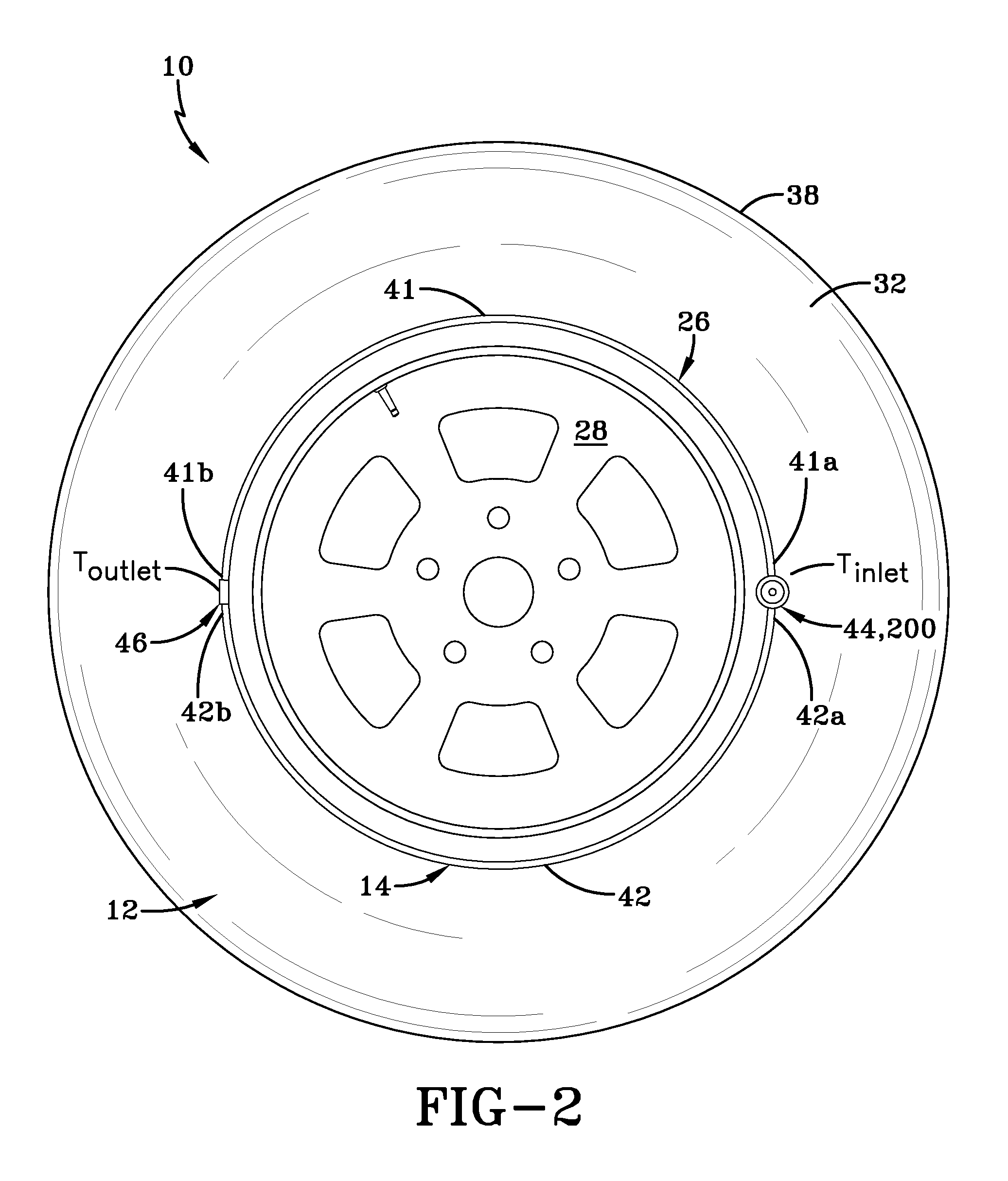
[0046]an inlet device 44 is shown in FIGS. 8-10. The inlet device functions to regulate the inlet flow of both pumps 41,42. The inlet device 44 includes an outer T shaped insert 60 that may be molded into a green tire and then cured. FIGS. 8-10 illustrate the inlet device installed in the sidewall 32 of a tire, wherein the T shaped portion of the insert is located on the interior portion of the tire sidewall, facing the tire cavity 40. An outer face 61 of the insert is preferably flush with the tire sidewall 32. The insert 60 has an inner chamber 62 formed by sidewalls 63 and bottom wall 64. Two holes 65,66 are located in the inner chamber sidewall 63 for fluid communication with inlet tube ends 41,42a of the pumps 41,42.

[0047]A regulator body 68 is received within the inner chamber 62 of the insert through threaded hole 69 of the outer face 61. Preferably, the outer surface of the regulator body is threaded, so that the regulator body can be screwed in or out of the threaded hole 6...

second embodiment

[0050]an inlet device 200 is shown in FIGS. 11-14. The inlet device functions to regulate the inlet flow of both pumps 41,42. The inlet device 200 includes an outer T shaped insert 210 that may be molded into a green tire and then cured. FIG. 14 illustrates the inlet device installed in the sidewall 32 of a tire, wherein the T shaped portion of the insert is located on the interior portion of the tire sidewall, facing the tire cavity 40. An outer face 212 of the insert is preferably flush with the tire sidewall 32. The insert has an inner chamber 220 formed by sidewalls 222 and bottom wall 224. Two holes 226,228 are located in the inner chamber sidewall 222 for fluid communication with inlet tube ends 41,42a of the pumps 41,42.

[0051]A regulator piston 230 is slidably received within the inner chamber 220 of the insert. The regulator piston 230 has an outer flanged surface 232 which is slidably received within a slot 234 of the chamber sidewall. An outer stop 236 located on the upper...


PUM


Abstract

A self-inflating tire assembly includes an air tube connected to a tire and defining an air passageway, the air tube being composed of a flexible material operative to allow an air tube segment opposite a tire footprint to flatten, closing the passageway, and resiliently unflatten into an original configuration. The air tube is sequentially flattened by the tire footprint in a direction opposite to a tire direction of rotation to pump air along the passageway to an inlet device for exhaust from the passageway or to an outlet device for direction into the tire cavity. The inlet device is positioned within the annular passageway 180 degrees opposite the outlet device such that sequential flattening of the air tube by the tire footprint effects pumping of air along the air passageway with the tire rotating in either a forward or reverse direction of rotation. The invention further includes an inlet device for regulating the inlet flow of the air tube pump.

Description

FIELD OF THE INVENTION[0001]The invention relates generally to self-inflating tires and, more specifically, to a pump mechanism for such tires.BACKGROUND OF THE INVENTION[0002]Normal air diffusion reduces tire pressure over time. The natural state of tires is under inflated. Accordingly, drivers must repeatedly act to maintain tire pressures or they will see reduced fuel economy, tire life and reduced vehicle braking and handling performance. Tire Pressure Monitoring Systems have been proposed to warn drivers when tire pressure is significantly low. Such systems, however, remain dependant upon the driver taking remedial action when warned to re-inflate a tire to recommended pressure. It is a desirable, therefore, to incorporate a self-inflating feature within a tire that will self-inflate the tire in order to compensate for any reduction in tire pressure over time without the need for driver intervention.SUMMARY OF THE INVENTION[0003]The invention provides in a first aspect a self-i...

Claims


Application Information

Patent Timeline
IPC IPC(8): B60C19/00B60C5/00
CPCY10T152/10495B60C23/12B60C23/123B60C23/135
Inventor HINQUE, DANIEL PAUL LUC MARIE
Owner THE GOODYEAR TIRE & RUBBER CO
Why Eureka
Try Eureka