Control device with adjusting pulse width modulation function and the backlight module thereof

a control device and pulse width technology, applied in pulse technique, process and machine control, instruments, etc., can solve the problems of difficult control of color temperature of white light, difficult control of color temperature and illuminant of led array, and difficult control of white light color temperature and other issues to achieve the effect of power saving

Inactive Publication Date: 2013-02-28
LUXMILL ELECTRONICS
View PDF4 Cites 10 Cited by
  • Summary
  • Abstract
  • Description
  • Claims
  • Application Information

AI Technical Summary

Benefits of technology

[0011]In order to solve the drawbacks described above, the main object of the present invention is to provide a voltage converter with a sampling-hold and integrating circuit. According to the minimum different value generated by the practical status of each of the illuminant channels in the LED backlight module, the sampling-hold and integrating circuit will generate a superposition voltage by superposition theory and the voltage converter can output an analog signal to drive each of the illuminant channels in the backlight module. When the sampling-hold and integrating circuit of the voltage converter and the control device with adjusting pulse width function are embedded together to provide to the LED backlight module, the power saving is more convenient.

Problems solved by technology

Because the CCFL light tube implements the mercury (HG) to be the illuminant light source, the mercury will cause the environmental protection problem during manufacturing and recycling.
One of the significant drawbacks in the LED direct backlight module is the illuminant of the individual LEDs is not all the same, especially when red light, green light and blue light LEDs are together to generate white light.
The color temperature of the white light is difficult to control.
Therefore, it is difficult to control the color temperature and the illuminant of the LED array.
However, those methods are required lots of memory, and those technologies are hard to be embedded in one chip.
Obviously, the equivalent circuit in FIG. 1C is not able to change the duty cycle and the phase of the PWM signal.
However, the difficulty of the circuit design is increased and a feedback pin is added in the chip, so the manufacture cost is increased.

Method used


Image

  • Control device with adjusting pulse width modulation function and the backlight module thereof
  • Control device with adjusting pulse width modulation function and the backlight module thereof
  • Control device with adjusting pulse width modulation function and the backlight module thereof

Examples


Embodiment Construction

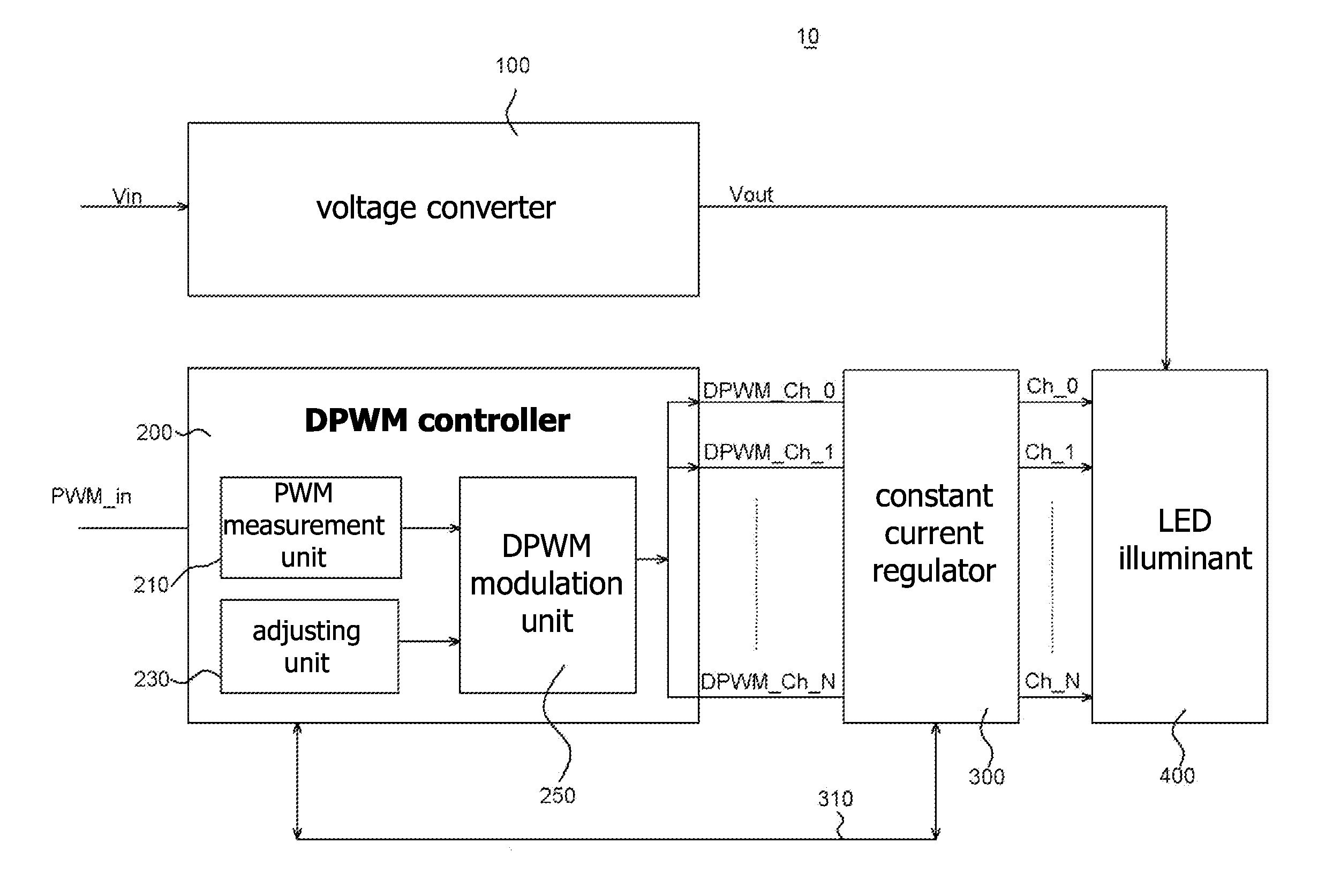
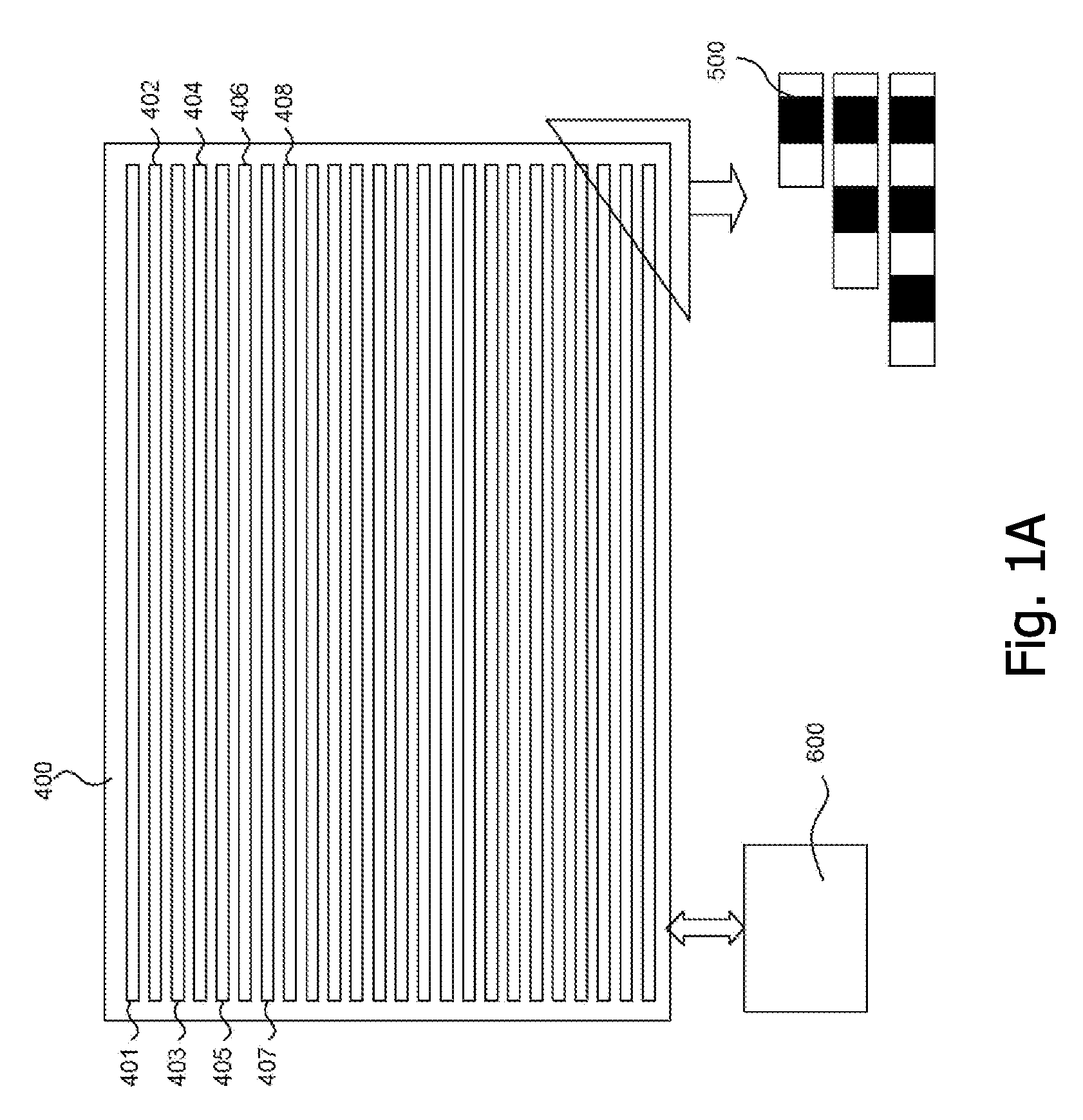
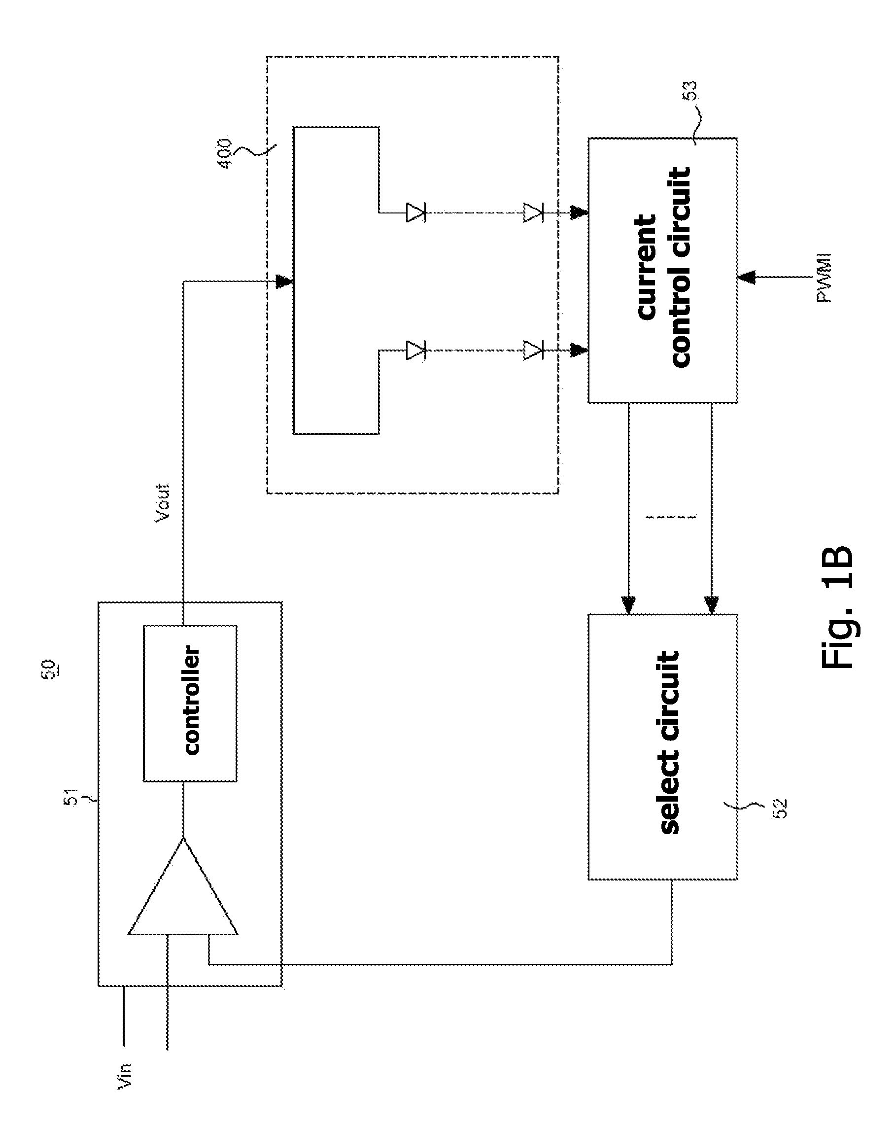
[0031]The present invention is an adjusting apparatus of the light emitting diode (LED) backlight module, and more particularly is to provide the most suitable pulse width modulation (PWM) in each of the channels of the LED backlight module before driving the LED backlight module. The technique description of the LED or the LED backlight module is based on the prior art, so the detail description thereof is omitted herein. The following is the detailed description of the present invention, which describes a method of fabricating an integral device of a biochip integrated with micro thermo-electric elements and the apparatus, but the detailed structure composition and the operating theory are not discussed. The portions relating to the conventional techniques are briefly described, and the parts of the drawings are not proportionally drafted. While embodiments are discussed, it is not intended to limit the scope of the present invention. Except expressly restricting the amount of the...


PUM


Abstract

A voltage converter with a sampling-hold and integrating circuit is provided herein. According to the minimum different value generated by the practical status of each of the illuminant channels in the LED backlight module, the sampling-hold and integrating circuit will generate an superposition voltage and the voltage converter can output different PWM signal to drive each of the illuminant channels in the backlight module. When the sampling-hold and integrating circuit of the voltage converter and the control device with adjusting pulse width function are embedded together to provide to the LED backlight module, the power saving is more convenient.

Description

[0001]The current application claims a foreign priority to the patent application of Taiwan No. 100130184 filed on Aug. 23, 2011.BACKGROUND OF THE INVENTION[0002]1. Field of the Invention[0003]The present invention is an adjusting device of the light emitting diode (LED) backlight module, and more particularly is to provide the most suitable pulse width modulation (PWM) in each of the channels of the LED backlight module before driving the LED backlight module.[0004]2. Description of the Prior Art[0005]The backlight module of the large scale Liquid Crystal Display (LCD) TV is using Cold Cathode Fluorescent Lamp (CCFL) or Light Emitting Diode (LED) to be the light source. Because the CCFL light tube implements the mercury (HG) to be the illuminant light source, the mercury will cause the environmental protection problem during manufacturing and recycling. In addition, the CCFL tube must be isolated from air to increase the life time. The LED technology is well developed and the illum...

Claims


Application Information

Patent Timeline
Patent Type & Authority Applications(United States)
IPC IPC(8): H05B37/02H03K7/08
CPCH03K7/08H05B33/0866H05B33/0827H05B45/24H05B45/46
Inventor CHEN, CHE-SHENGSUNG, HUNG-TA
Owner LUXMILL ELECTRONICS
Why Eureka
Try Eureka