
High Frequency Loss Measurement Apparatus and Methods for Inductors and Transformers

a technology of inductors and transformers, which is applied in the direction of instruments, magnetic measurements, measurement devices, etc., can solve the problems of complex loss measurement, inability to optimally optimize the efficiency of power circuits, and no satisfactory technique for measuring core losses in inductors and/or transformers is known

Active Publication Date: 2013-02-28
VIRGINIA TECH INTPROP INC
View PDF16 Cites 16 Cited by
  • Summary
  • Abstract
  • Description
  • Claims
  • Application Information

AI Technical Summary

Benefits of technology

This patent describes a method and apparatus for measuring the losses in high-frequency inductors and transformers. The method involves resonating the winding with a reactive component in a series resonant circuit to cancel out a portion of the reactive voltage of the magnetizing inductance. The value of the reactive component is chosen so that the measured voltage has a phase difference of less than 80 degrees with the measured current in the circuit. The measured voltage and current are then integrated to get a more accurate measurement of the magnetic core loss. The apparatus includes a sensing winding, a current sensor, and the reactive component. The technical effect of this patent is to provide a reliable and accurate method for measuring the losses in high-frequency inductors and transformers.

Problems solved by technology

Since a power supply circuit does not otherwise contribute to the function of the electronics, its efficiency is of paramount importance since it directly detracts from the overall efficiency of the device.
For this reason, losses attributable to inductors and transformers which are generally included in such power circuits are important concerns.
The power circuit cannot be optimally efficient without proper magnetic cores for such passive elements while accurate measurement of inductor and transformer losses is necessary for proper inductor and transformer core design.
Further, requirements for so-called point-of-load power circuits where size and power density are particularly critical have favored the use of high frequency switching which complicates loss measurement, as will be discussed in greater detail below.
Unfortunately, no satisfactory technique for measurement of core losses in inductors and / or transformers is currently known.
The techniques currently in use for this purpose, while providing reasonably useful results, present difficulties and sources of error such as compensation for winding losses which are difficult to estimate or extreme sensitivity to measurement discrepancy in regard to parameters which are subject to errors that may be engendered in whole or in part by the instrumentation required for the measurement, as will be discussed in greater detail below.

Method used


Image

  • High Frequency Loss Measurement Apparatus and Methods for Inductors and Transformers
  • High Frequency Loss Measurement Apparatus and Methods for Inductors and Transformers
  • High Frequency Loss Measurement Apparatus and Methods for Inductors and Transformers

Examples


Embodiment Construction

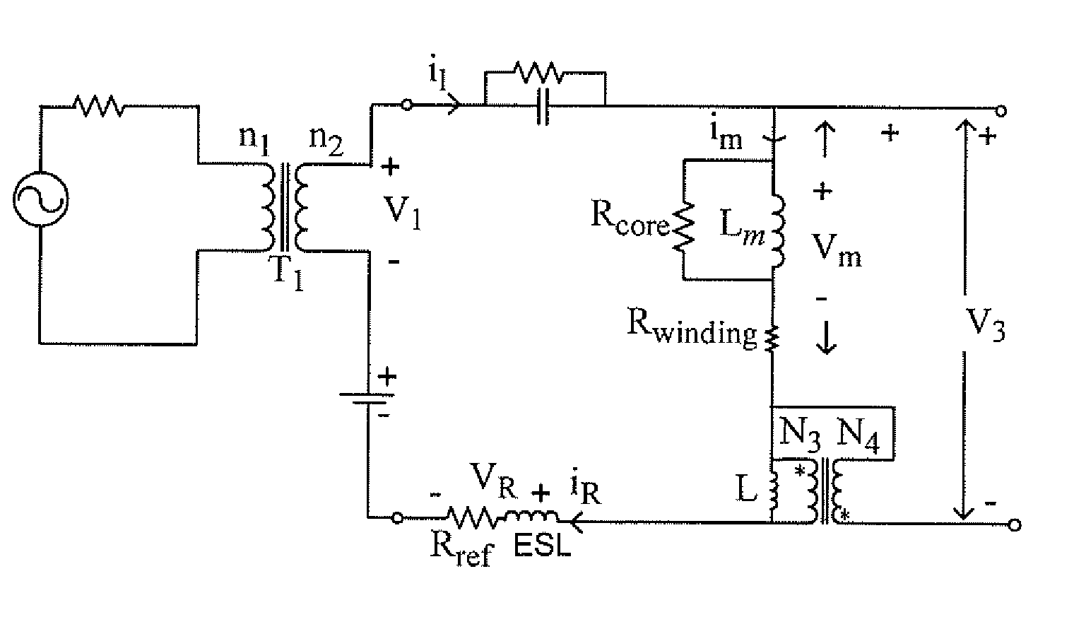
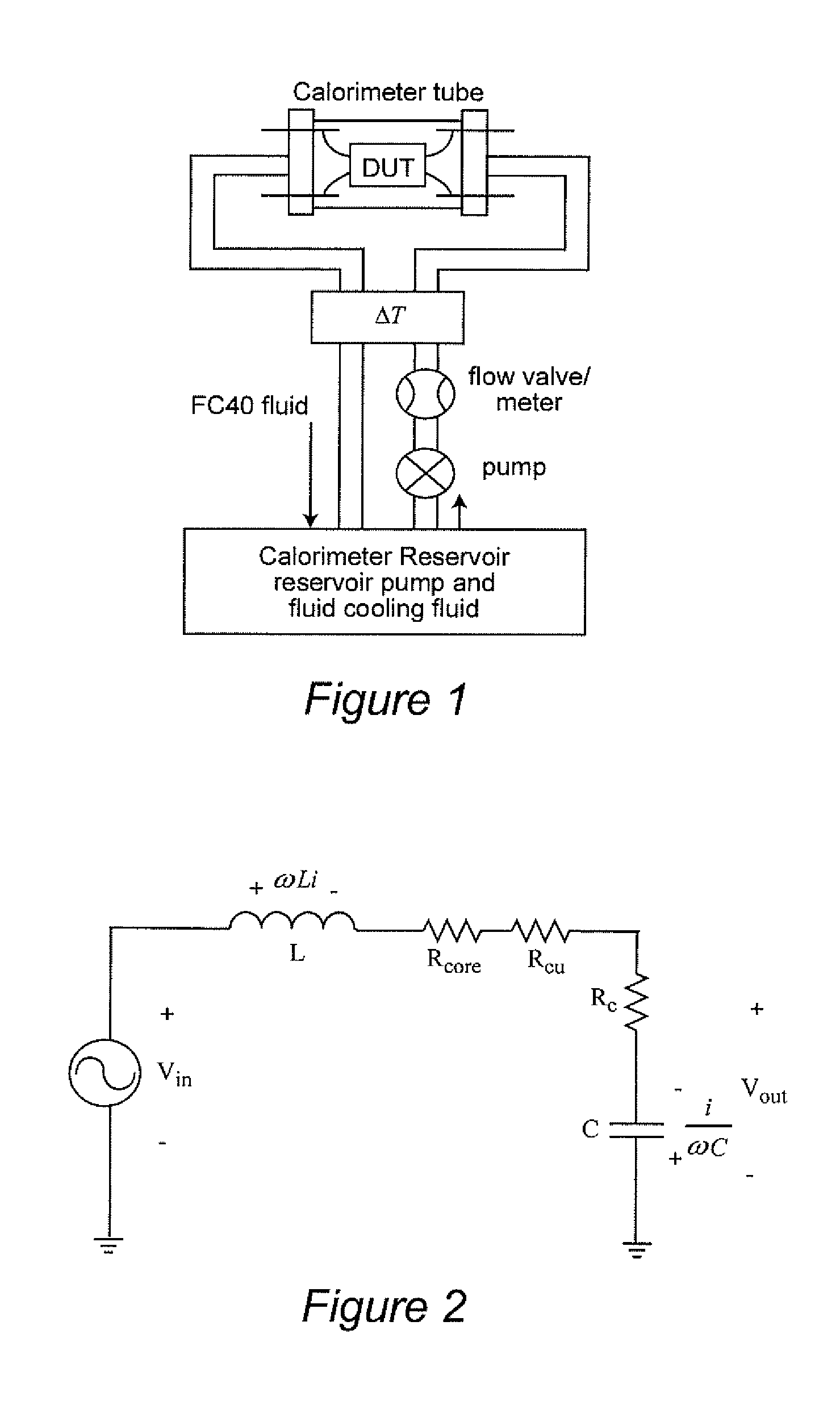
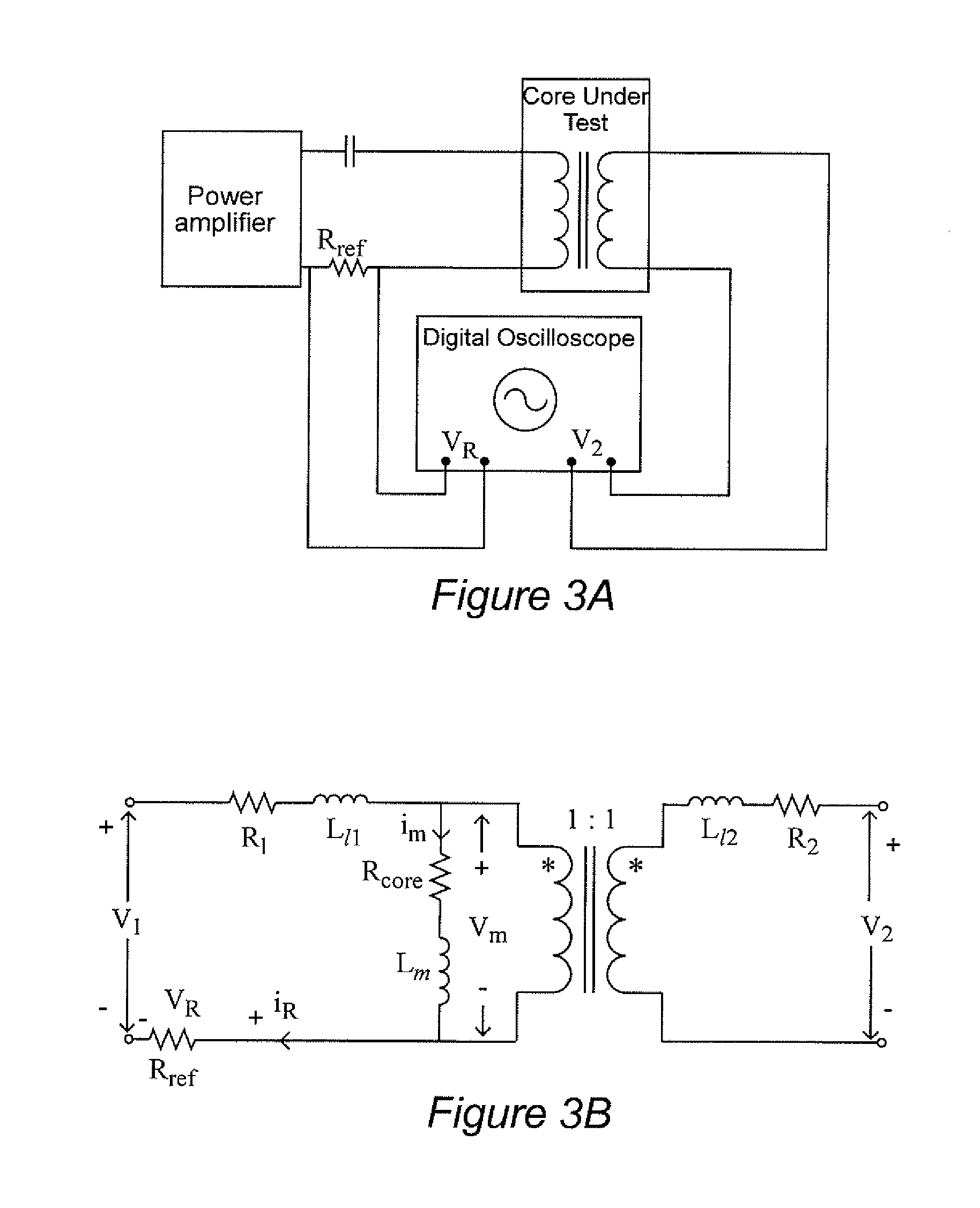
[0030]Referring now to the drawings and more particularly to FIGS. 1-3, several known measurement methods for obtaining core loss information are illustrated and will be discussed in turn. It is to be understood that, while FIGS. 1-3 do not illustrate the invention and are directed to known measurement methods, the illustrations of FIGS. 1-3 are also arranged to facilitate conveyance of an understanding of the problems addressed and overcome by the invention as well as allowing a more complete appreciation of the meritorious effects of the invention. Therefore, no portion of any of FIGS. 1-3 is admitted to be prior art in regard to the present invention.

[0031]One universally applicable and frequency-independent but relatively crude and indirect known approach to loss measurement is through a thermal approach in which the basic method is to put the device under test (DUT) in a thermally isolated chamber through which a fluid is circulated and to measure the temperature difference of ...


PUM


Abstract

Core loss in an inductor is measured with reduced sensitivity to phase measurement error by connecting a reactive component to resonate with the inductor and thus cancel a portion of the reactive voltage on the inductor; reducing the phase difference between the inductor voltage and current and making the observed power more resistive. The reactive component may be a capacitor for sinusoidal excitation or an inductance such as an air core transformer for arbitrary excitation.

Description

FIELD OF THE INVENTION[0001]The present invention generally relates to power electronics applications such as power supplies and regulators and, more particularly, to accurate measurement of losses in inductors and transformers used therein for optimization of their design.BACKGROUND OF THE INVENTION[0002]Virtually all currently available devices that includes any electronic circuits include a power supply circuit to ensure that appropriate power is delivered thereto for the electronic circuits to properly perform their intended functions. Since a power supply circuit does not otherwise contribute to the function of the electronics, its efficiency is of paramount importance since it directly detracts from the overall efficiency of the device. Thus, many sophisticated designs for power supplies, converters and regulators (hereinafter sometimes collectively referenced by the term power circuits) have been developed and have achieved relatively high efficiency which is difficult to inc...

Claims


Application Information

Patent Timeline
Patent Type & Authority Applications(United States)
IPC IPC(8): G01R33/14
CPCG01R33/14G01R33/1207
Inventor MU, MINGKAILEE, FRED C.
Owner VIRGINIA TECH INTPROP INC
Learn More