Decorative light with a changeable shade

a technology of decorative light and shade, which is applied in the direction of semiconductor devices for light sources, coupling device connections, lighting and heating apparatus, etc., can solve the problems of easy water infiltration into the shade, damage to the light source, and increase production costs, and achieve good waterproof

Inactive Publication Date: 2013-02-28
XU FEI
View PDF9 Cites 10 Cited by
  • Summary
  • Abstract
  • Description
  • Claims
  • Application Information

AI Technical Summary

Benefits of technology

[0008]The main object of the present invention is to provide a decorative light with a changeable shade and to obtain a good waterproof effect.
[0009]To achieve the foregoing objective, the decorative light in accordance with the present invention comprises a light source, two wires, a socket and a shade. The wires include top ends electrically connected to a bottom of the light source by welding. The socket is coated around the bottom of the light source and the top ends of the wires by injection molding. The shade covers the light source and is detachably mounted on the socket. The decorative light can provide a good waterproof effect because the socket seals an opening of the shade to prevent water from infiltrating inside the shade and damaging the light source. Besides, users can change shades having different shapes freely to make the decorative light attractive and interesting.

Problems solved by technology

However, under this method, both the light source and the shade easily move away from the socket and water easily infiltrates into the shade and damages the light source.
Besides, the assembly method increases production cost and lowers productivity.
However, the socket molded directly on the opening of the shade makes the shade unchangeable and thereby makes the decorative light tiresome and unexciting for the user.

Method used


Image

  • Decorative light with a changeable shade
  • Decorative light with a changeable shade
  • Decorative light with a changeable shade

Examples


first embodiment

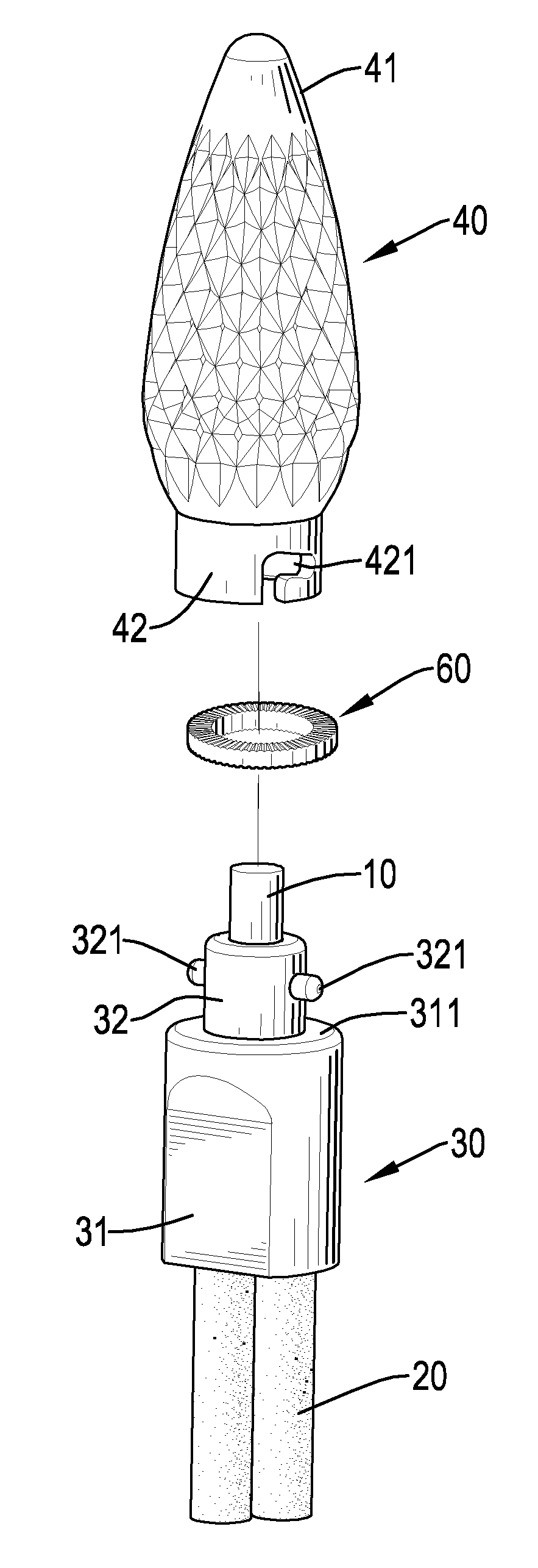
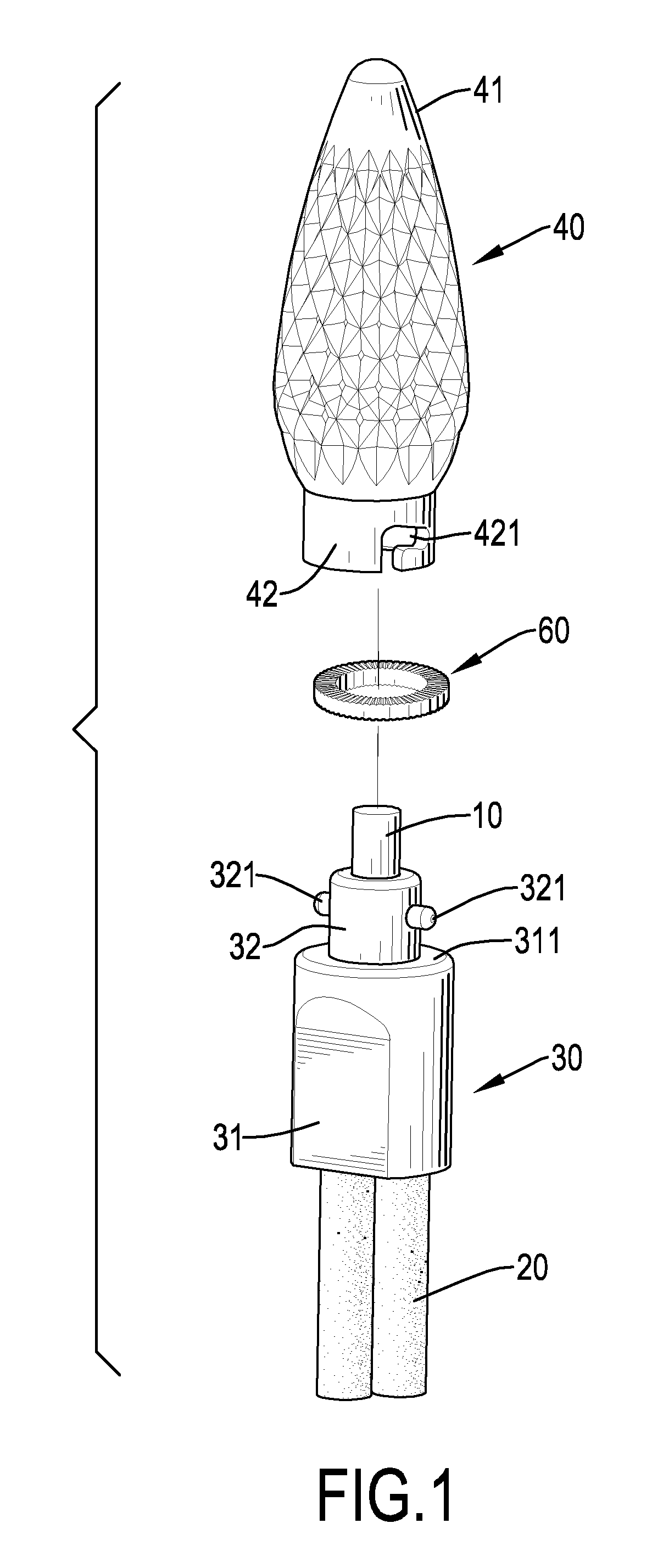
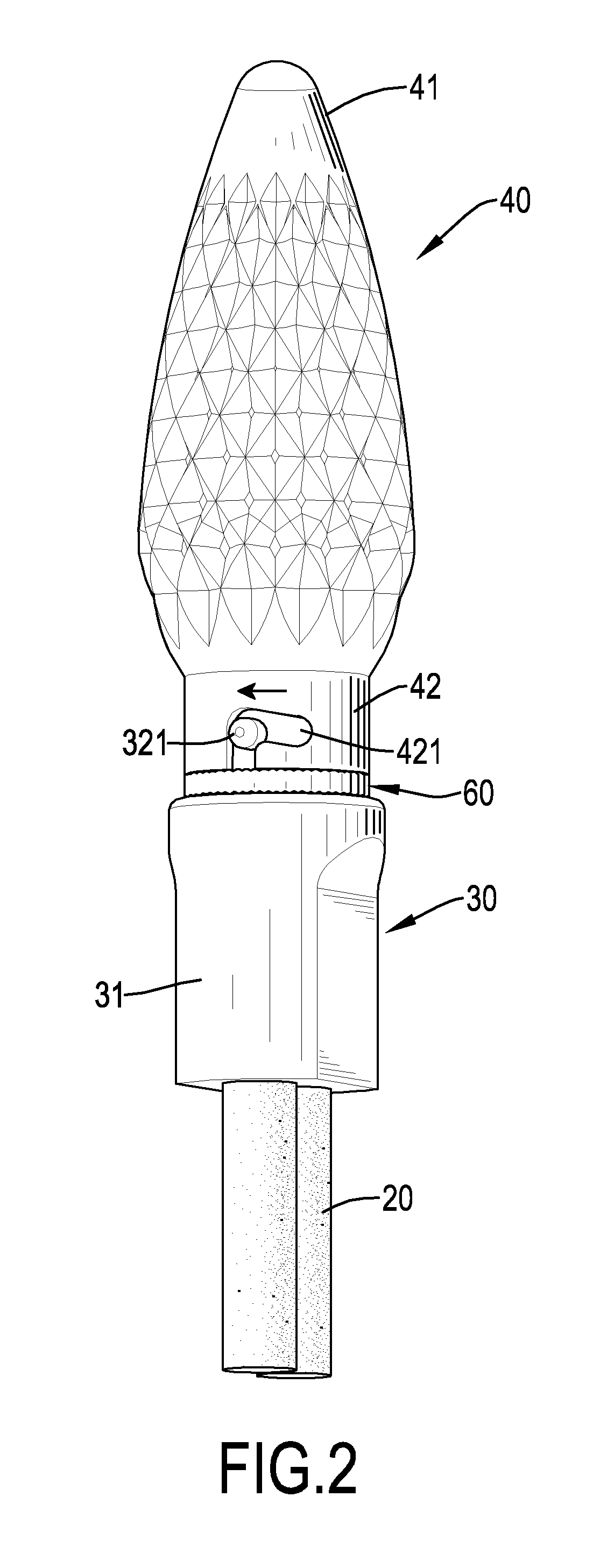
[0033]the decorative light further comprises a washer 60. The washer 60 is mounted around the inserted portion 32 of the socket 30 and is clamped between the peripheral surface 311 of the base 31 of the socket 30 and the collar 42 of the shade 40. An outer diameter of the washer 60 is not less than an outer diameter of the collar 42 of the shade 40. With reference to FIG. 6, the washer 60 includes two rough surfaces 61 formed respectively on an upper surface and a lower surface of the washer 60 so as to increase friction force between the collar 42 of the shade 40 and the washer 60 and between the peripheral surface 311 of the base 31 of the socket 30 and the washer 60 and thereby to ensure that the shade 40 is tightly sealed with the socket 30. Each of the rough surfaces 61 may have multiple V-shaped grooves formed radially in the upper surface and the lower surface of the washer 60.

[0034]With reference to FIG. 7, a second embodiment is based on the first embodiment, but the insert...

third embodiment

[0035]With reference to FIGS. 8, 9 and 9A, in a third embodiment, the socket 30B includes an annular channel 31B and an annular protrusion 32B. The annular channel 31B is formed in an upper surface of the socket 30B, corresponds to the collar 42B of the shade 40B and has an open top and an outer surface. The annular protrusion 32B protrudes from the outer surface of the annular channel 31B and is formed around the open top of the annular channel 31B. The collar 42B of the shade 40B has an annular protrusion 421B. The annular protrusion 421B is formed around and protrudes from the external surface of the collar 42B near the shell 41B. The collar 42B of the shade 40B is inserted into the annular channel 31B of the socket 30B to make the annular protrusion 421B of the collar 42B pass through and engage the annular protrusion 32B of the socket 30B. The annular protrusion 32B of the socket 30B and the annular protrusion 421B of the collar 42B are designed as curved-shape to facilitate as...

fifth embodiment

[0037]With reference to FIGS. 11, 12 and 12A, in a fifth embodiment, the socket 30D includes a base 31D and an inserted portion 32D. The inserted portion 32D is formed on and protrudes from an upper surface of the base 31D, corresponds to the collar 42D of the shade 40D and has an annular surface and at least one hook 321D. Each one of the at least one hook 321D is formed on and protrudes from the annular surface of the inserted portion 32D. The collar 42D of the shade 40D has an annular protrusion 421D formed around and protruding from the internal surface of the collar 42D. In a preferred embodiment, the inserted portion 32D of the socket 30D has two hooks 321D. The inserted portion 32D of the socket 30D is inserted into the collar 42D of the shade 40D to make the hooks 321D of the inserted portion 32D engage the annular protrusion 421D of the collar 42D of the shade 40D. The hooks 321D of the inserted portion 32D and the annular protrusion 421D of the collar 42D are designed as c...


PUM


Abstract

A decorative light includes a light source, two wires, a socket and a shade. The wires have top ends electrically connected to a bottom of the light source by welding. The socket is coated around the bottom of the light source and the top ends of the wires by injection molding. The shade covers the light source and is detachably mounted on the socket. The decorative light can provide a good waterproof effect because the socket seals an opening of the shade to prevent water from infiltrating inside the shade and damaging the light source. Besides, users can change shades having different shapes freely to make the decorative light attractive and interesting.

Description

BACKGROUND OF THE INVENTION[0001]1. Field of the Invention[0002]The present invention relates to a decorative light, and more particularly to a decorative light with a changeable shade.[0003]2. Description of the Prior Arts[0004]Decorative lights are small colorful lights for decoration or advertisement. A conventional decorative light generally comprises a socket, a light source, two wires and a shade. The light source is mounted on the socket. The wires are electrically connected to the light source. The shade covers the light source and is mounted on the socket. Conventional decorative lights can be produced by an assembly method or an injection molding method.[0005]Steps of assembly method of producing the decorative lights are welding the wires to the light source first, then inserting the light source in the socket and finally mounting the shade on the socket. However, under this method, both the light source and the shade easily move away from the socket and water easily infi...

Claims


Application Information

Patent Timeline
Patent Type & Authority Applications(United States)
IPC IPC(8): H01R33/00
CPCF21S4/001F21S6/001F21S10/04F21Y2101/02F21V17/06F21V17/14F21V5/00F21S4/10F21Y2115/10
Inventor XU, FEI
Owner XU FEI
Why Eureka
Try Eureka