
Spinnaker sails from interwoven straps for generating electric power from wind

a technology of interwoven straps and spinnaker sails, which is applied in the direction of wind motors, motors, machines/engines, etc., can solve the problems of low permeability to air flow, high wind speed, and inability to withstand wind, so as to achieve large mechanical pulling forces

Inactive Publication Date: 2013-02-28
KELLY PATRICK D
View PDF31 Cites 23 Cited by
  • Summary
  • Abstract
  • Description
  • Claims
  • Application Information

AI Technical Summary

Benefits of technology

The patent describes new types of spinnakers that use high-strength straps interwoven in a way that allows for open space between them. These devices, which are called "webbing sails" or "web sails," are designed to work with buoyant lifting devices to capture and harness wind energy. This results in large mechanical pulling forces that can be used to generate electricity. Web sails are designed to operate at wind speeds of over 100 or even 150 miles per hour.

Problems solved by technology

Wind speeds that high would rapidly rip apart any conventional spinnaker sail of the type used on a sailboat.
Even though ropes made of natural fibers could be used as described herein, they will degrade much more rapidly, when used outdoors, than cables made of synthetic materials suited for outdoor use.
Any fabric made from woven or knitted fibers will inevitably have some degree of permeability, to air and wind; however, since “tight weaves” are used to make sailcloth, and since the types of fibers used to make sailcloth tend to be “fluffy” when seen under a microscope, in a manner which enables them to create nearly airtight seals between adjacent strands, permeability to air flow, in any conventional sailcloth material, is very low, and close to negligible.
Factors such as how much fabric was used to make the parachute, or how high its dome might extend when in use, will have no effect on its projected area, and little if any effect on whether it will be able to safely hold and land a person or cargo package having a certain weight.
However, the height of a parachute dome has essentially zero effect on how rapidly a person or item will descend, when hanging from that parachute.
However, narrow or rigid design parameters do not apply, when it comes to airborne spinnaker sails.
However, 100 or even 150 mph winds are not rare, or even especially unusual, at elevated altitudes.

Method used


Image

  • Spinnaker sails from interwoven straps for generating electric power from wind
  • Spinnaker sails from interwoven straps for generating electric power from wind
  • Spinnaker sails from interwoven straps for generating electric power from wind

Examples


Embodiment Construction

[0092]To ensure that the “disclosure of the best mode” requirement is fully satisfied, the entire discussion below is identical to the “Detailed Description” section in simultaneously-filed U.S. application Ser. No. 13 / 217,873. The section below which is directly pertinent to the “webbing sail” invention claimed herein is in a section below which is entitled, “WEBBING (OR WEB) SAILS”, and in FIGS. 20 and 21.

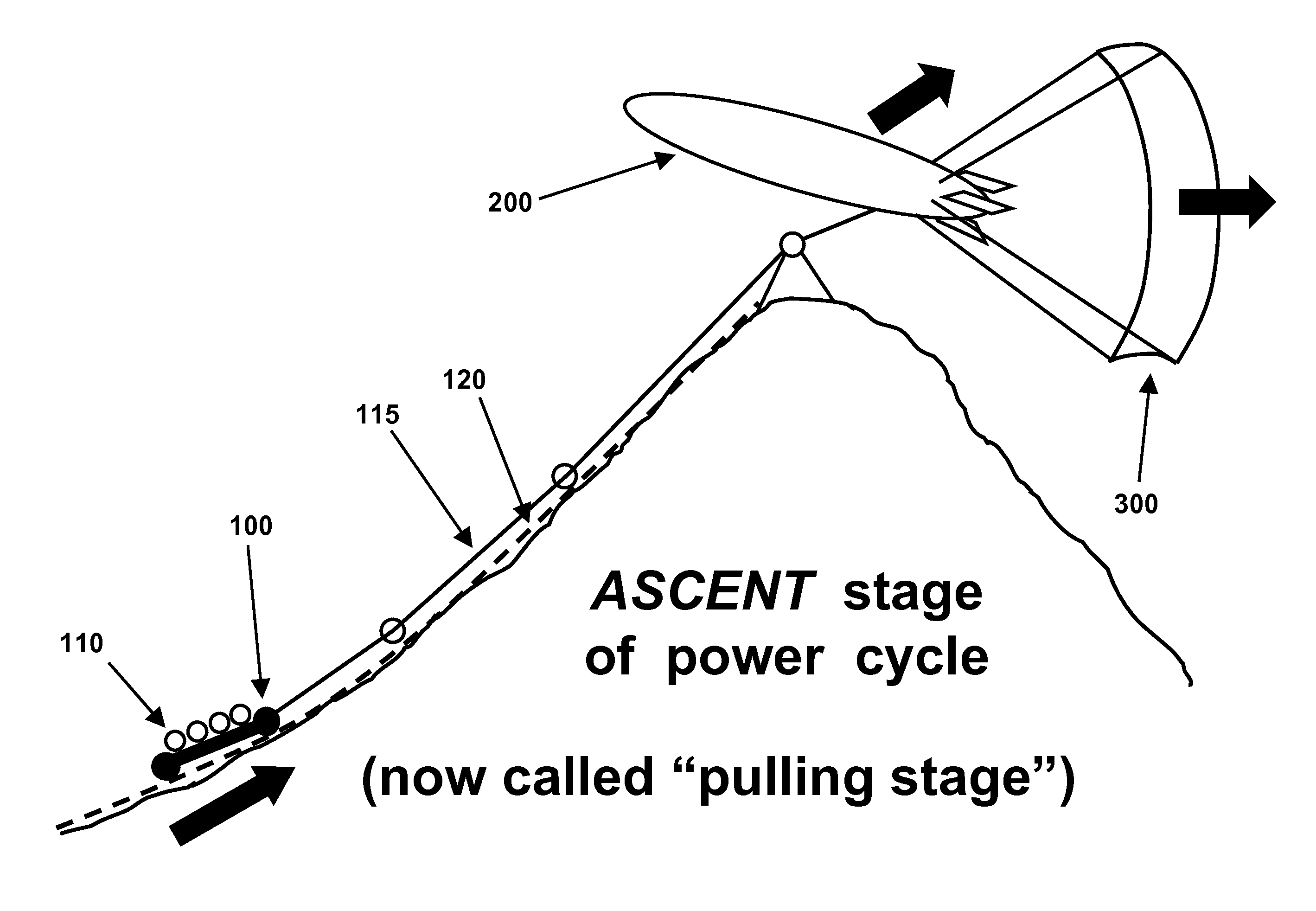
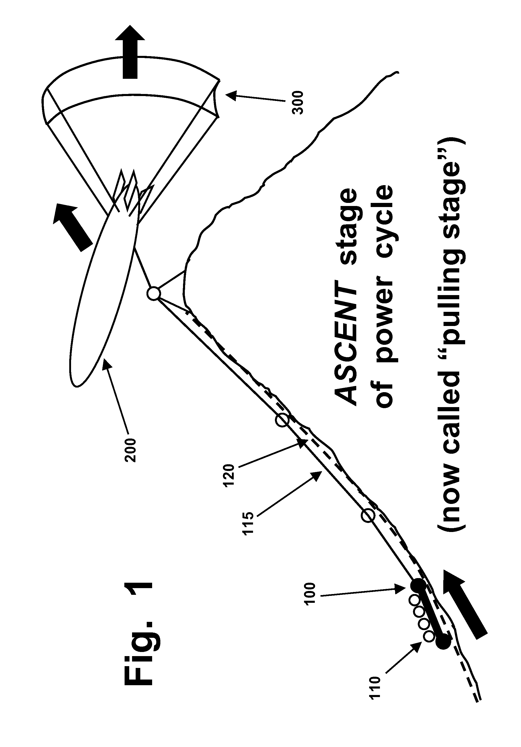
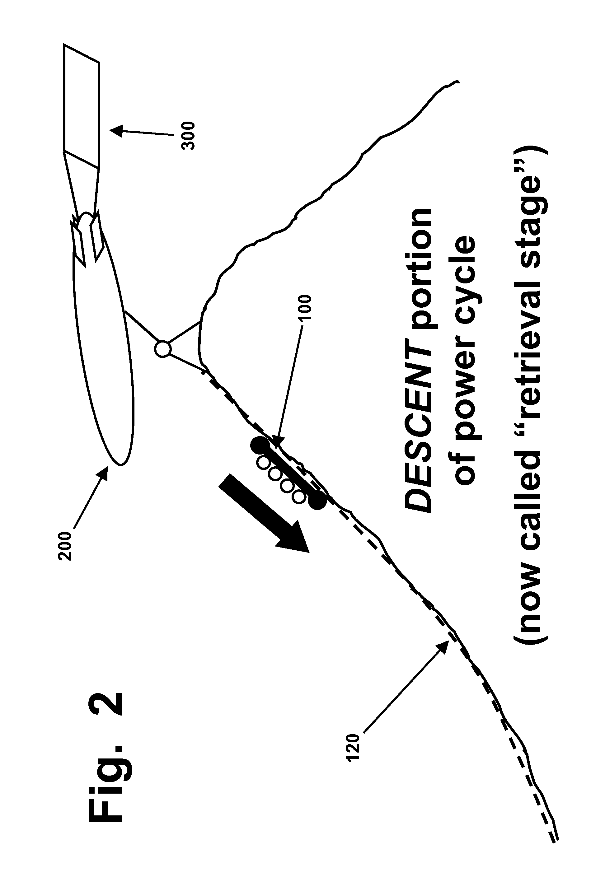
[0093]As briefly summarized above, this application discloses devices and methods that are designed to generate electric power, by capturing (or harvesting, converting, or similar terms) wind energy. One such device disclosed herein is an airborne traveling assembly referred to herein as an“airbarge and sail” unit (or system, assembly, etc.). It uses an airbarge (i.e., a wide and flat lifting device which will be unmanned during normal use), which is buoyant (i.e., filled with enough hydrogen or helium to overcome the weight of both the airbarge and the sail, in a manner which ge...


PUM


Abstract

New types of “airborne spinnaker sails” are disclosed, made from high-strength straps that are interwoven in a manner that preserves open space between them. These devices, referred to as “webbing sails” or simply “web sails”, are designed for use in conjunction with buoyant lifting devices, to capture and harvest wind energy in a way which will generate large mechanical pulling forces, which can be used to drive electric power generators. These types of web sails are designed to operate in winds that exceed 100 or even 150 miles per hour.

Description

BACKGROUND[0001]This invention is in the field of electromechanical systems, and relates to the use of specialized types of spinnaker sails, to convert wind energy into electric power.[0002]This application involves a new type of “airborne spinnaker sail”, which will function as a component or subassembly within a larger electromechanical system which has been described in U.S. patent application Ser. No. 12 / 390,503, which was published on Aug. 26, 2010 as 20100213718. All teachings and disclosures set forth in that application are incorporated herein, as though fully set forth herein.[0003]In addition, this application is being filed simultaneously with a continuation-in-part application which claims the benefit and priority date of U.S. Ser. No. 12 / 390,503. That C-I-P application has been given Ser. No. 13 / 217,873, and its entire teachings and contents are incorporated by reference, as though fully set forth herein. It was designated as a C-I-P application, since its teachings and...

Claims


Application Information

Patent Timeline
IPC IPC(8): F03D5/00
CPCF03D5/00Y02E10/70F03D5/04
Inventor KELLY, PATRICK D.
Owner KELLY PATRICK D
Learn More